MAN00000772_SI-G200BB_SVCPDFA.pdf - 第146页
O perati onGuide W o rkPr ocess PartsReplacem ent M ai nt enance I n te nd e d i t em S I -G200 AA BB Docume n t no.W KGB- 2010 5 -0 1 Page 4/8 2. T a k i n gof f…
OperationGuide WorkProcess PartsReplacement Maintenance
Intendeditem SI-G200AABB
Documentno.WKGB-20105-01
Page 3/8
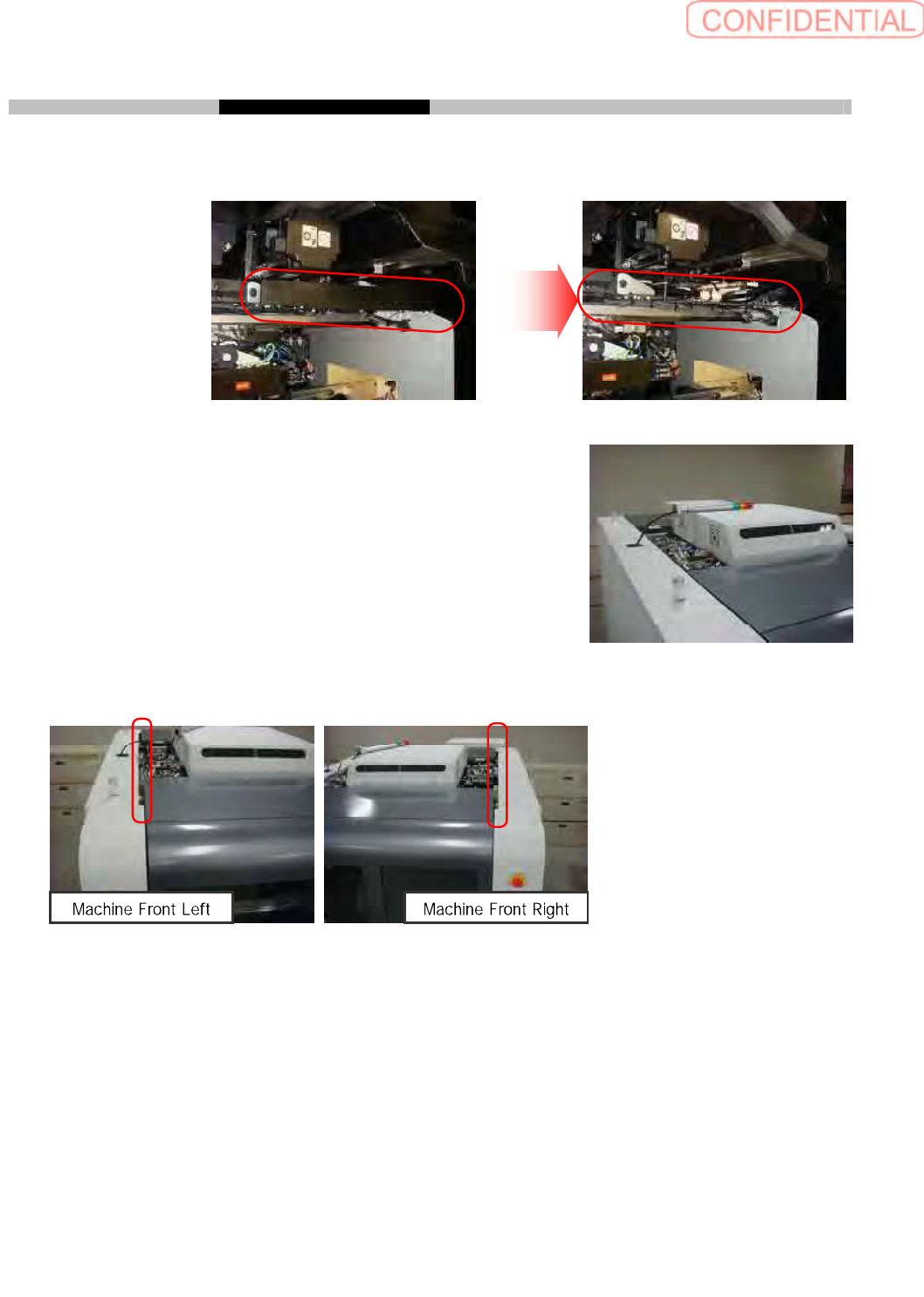
Loosen 8 CP 3 x 6 to take off head connector cover of front side.
Take off head connector cover of rear side as same way.
Loosen 4 CP 4 x 15 to move tower light position from side
sealing to machine top center. It is not requires to take off the
connector which connects tower light and machine.
Loosen 2 CP4 x 8 to shift side sealing position by 10 mm to machine outside.
Now preparation is completed.
OperationGuide WorkProcess PartsReplacement Maintenance
Intendeditem SI-G200AABB
Documentno.WKGB-20105-01
Page 4/8
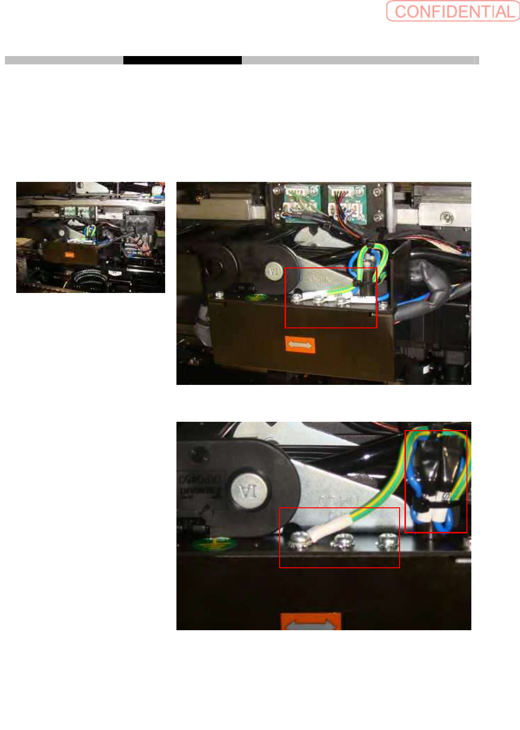
2. TakingoffSHterminalsoffeedcover
Loosen 2 P4 x 6 to take off SH terminal on feed cover. After taking off SH terminals fix 2 P4 x 6
and tooth lock washers.
Wrap SH Terminal with plastic tape to fix nylon tie
This process should be done for front and rear side.
Work spot
Enlarged
Enlarged (completed)
OperationGuide WorkProcess PartsReplacement Maintenance
Intendeditem SI-G200AABB
Documentno.WKGB-20105-01
Page 5/8
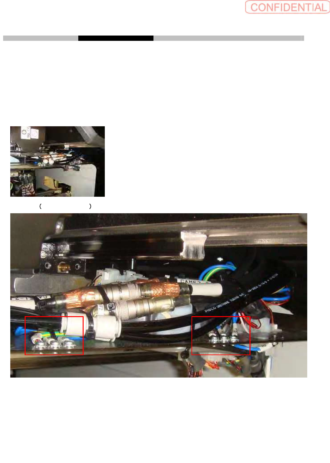
3. TakingoffSHterminalsofX-Yrelay
Loosen 4 P4 x 6 to take off SH terminal on cable relay plate. It is not necessary taking off SH
terminals which is from
XFM2(XRM2)
beneath cable relay plate
.
After taking off SH terminals fix 4
P4 x 6 and tooth lock washers.
Wrap SH Terminal with plastic tape to fix nylon tie
This process should be done for each by 2 spots on right and left side.
Work spot
Enlarged 2 spots, left side