MAN00000772_SI-G200BB_SVCPDFA.pdf - 第148页
O perati onGuide W o rkPr ocess PartsReplacem ent M ai nt enance I n te nd e d i t em S I -G200 AA BB Docume n t no.W KGB- 2010 5 -0 1 Page 6/8 Enl a rg ed ( Comp l …
OperationGuide WorkProcess PartsReplacement Maintenance
Intendeditem SI-G200AABB
Documentno.WKGB-20105-01
Page 5/8
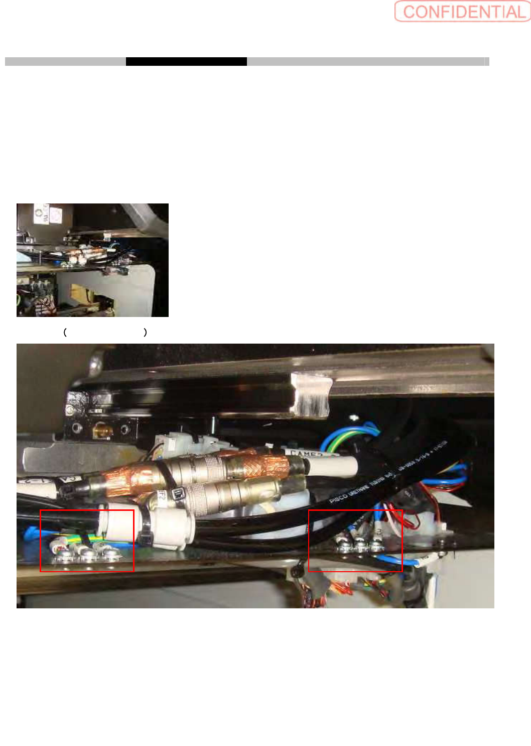
3. TakingoffSHterminalsofX-Yrelay
Loosen 4 P4 x 6 to take off SH terminal on cable relay plate. It is not necessary taking off SH
terminals which is from
XFM2(XRM2)
beneath cable relay plate
.
After taking off SH terminals fix 4
P4 x 6 and tooth lock washers.
Wrap SH Terminal with plastic tape to fix nylon tie
This process should be done for each by 2 spots on right and left side.
Work spot
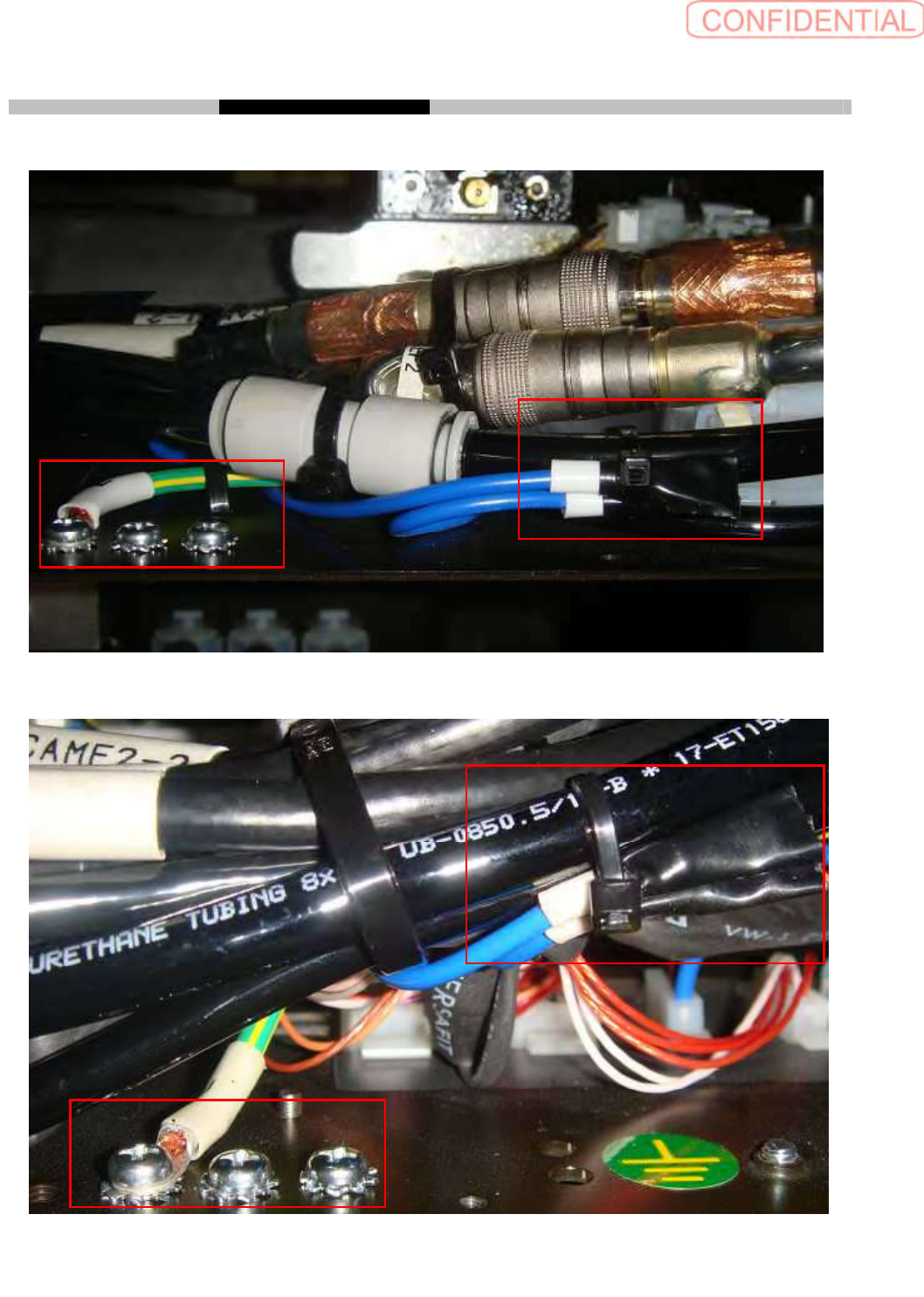
Enlarged 2 spots, left side
OperationGuide WorkProcess PartsReplacement Maintenance
Intendeditem SI-G200AABB
Documentno.WKGB-20105-01
Page 6/8
Enlarged (Completed 2 spots, left side)
Enlarged (Completed 2 spots, right side)
OperationGuide WorkProcess PartsReplacement Maintenance
Intendeditem SI-G200AABB
Documentno.WKGB-20105-01
Page 7/8
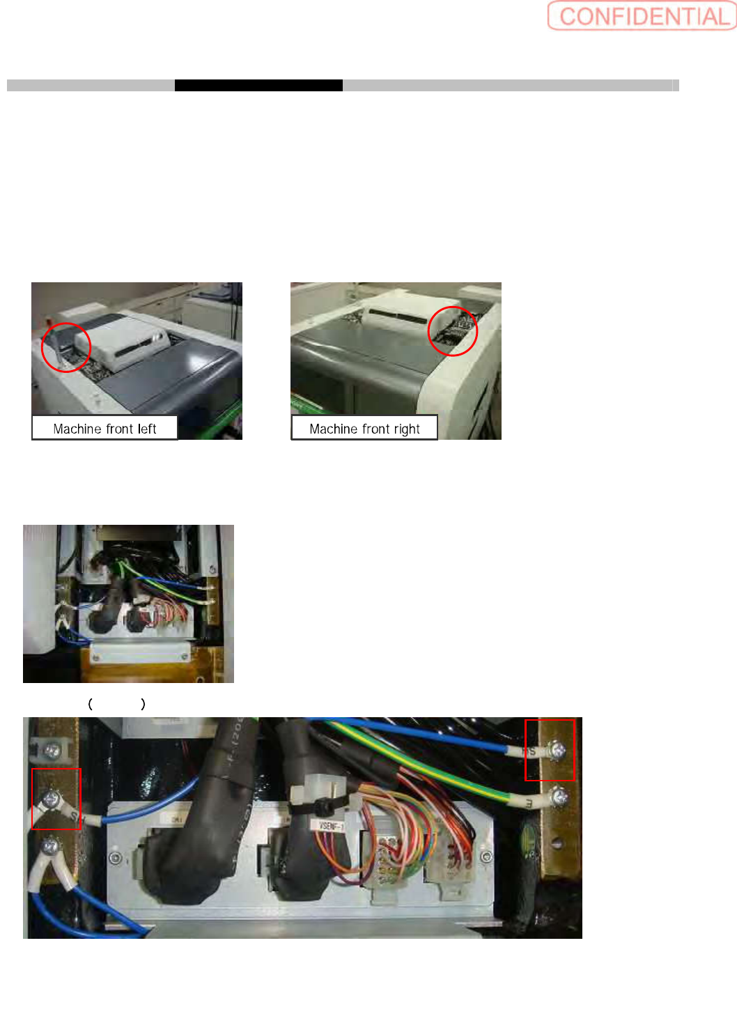
4. TakingoffSHterminalsofupperframe
Loosen 2 P4 x 6 to take off SH terminal from XFM1 (XRM1), XFM2 (XRM2). After taking off SH
terminals fix 2 P4 x 6 and tooth lock washers.
Wrap SH Terminal with plastic tape to fix nylon tie
This process should be done for front and rear side.
Y Cable rear side Y Cable front side
Work spot
Enlarged 2 spots