MAN00000772_SI-G200BB_SVCPDFA.pdf - 第155页
HLGB-10101-01 Insta ll the Calibration Plate Jig Operations to use the calibration plate jig are as fol l ows. When perf orming the following operati o ns, install the calibration pl a te jig ac cording to the procedure …

CLGB-10106-01
SI-G200BB Service Manual
"Console Operation Procedure
Contents"
SHEET
2/2
Pickup Position Setup................................................................. HLGB-10311-01
Checking Pickup Position ........................................................... HLGB-10312-01
Mount Accuracy Calibration........................................................ HLGB-10313-01
XY Axis Software Limit Setup ..................................................... HLGB-10314-01
Conveyor Width Adjustment ....................................................... HLGB-10315-01
Measuring Parallelism of Reference Pin and Dependent Pin ..... HLGB-10316-01
Parts Discard Position Adjustment.............................................. HLGB-10317-01
2-4 Adjustment
Matching of X Axis Z-Phase ....................................................... HLGB-10401-01
Matching of Y Axis Z-Phase........................................................ HLGB-10402-01
H Axis Gear Z-phase Matching................................................... HLGB-10403-01
Adjustment of H Axis Upper End OT Sensor (H-CCW) .............. HLGB-10404-01
Adjustment of H axis Lower End OT Sensor (H-CW) ................. HLGB-10405-01
FF/FR Axis Z-Phase Matching.................................................... HLGB-10406-01
Adjustment of FF/FR Axis Belt Tension ...................................... HLGB-10407-01
Adjustment of RTF/RTR Axis Belt Tension ................................. HLGB-10408-01
Adjustment of RNF/RNR Axis Belt Tension ................................ HLGB-10409-01
Gap Adjustment for Head Unit Mechanical Valve and Plunger... HLGB-10410-01
Adjustment of Plunger Upper/Lower Backward Detect Sensor .. HLGB-10411-01
Nozzle Height Adjustment .......................................................... HLGB-10412-01
Nozzle Escape Detect Sensor Position Adjustment ................... HLGB-10413-01
Phase Adjustment for Nozzle ..................................................... HLGB-10414-01
Nozzle Sensor Adjustment ......................................................... HLGB-10415-01
Adjustment of PWB Sensor ........................................................ HLGB-10416-01
Adjustment of Cassette Float Sensor Height.............................. HLGB-10417-01
Adjustment of PWB Stopper Sensor........................................... HLGB-10418-01
Fixed Camera Pickup Check Sensor Adjustment ....................... HLGB-10419-01
Area Sensor Light Axis Adjustment............................................. HLGB-10420-01
Ejector Setup.............................................................................. HLGB-10421-01
Blow Flow rate Setup.................................................................. HLGB-10422-02
Vacuum Pump Sensor Setup ..................................................... HLGB-10423-01
Supplied Air Sensor Setup.......................................................... HLGB-10424-01
Adjustment and checking of H-axis software limit....................... HLGB-10425-01
HLGB-10101-01
Install the Calibration Plate Jig
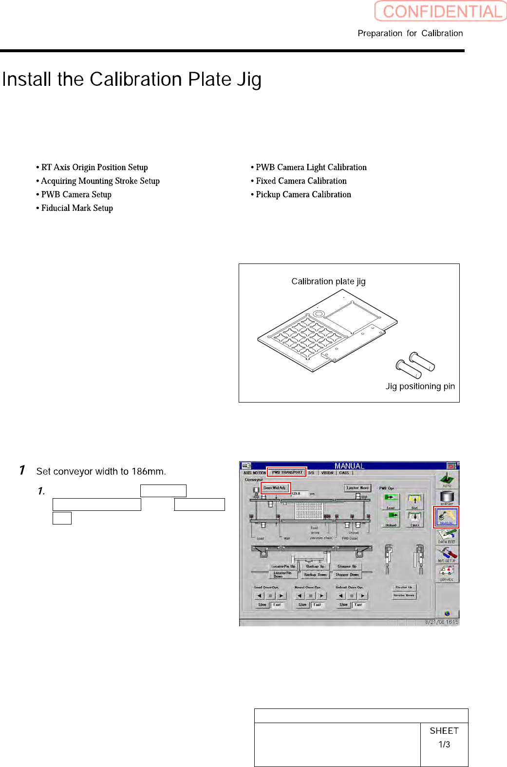
Operations to use the calibration plate jig are as follows.
When performing the following operations, install the calibration plate jig according to the procedure
described in this section.
Set-Up
Calibration
[Necessary jigs]
•
Calibrationplatejig
• Jig positioning pin
[Procedure]
Click in an order of MANUAL menu
PWB TRANSPORT tab Conv. Wid.
Adj. button.
HLGB-10101-01
Install the Calibration Plate Jig
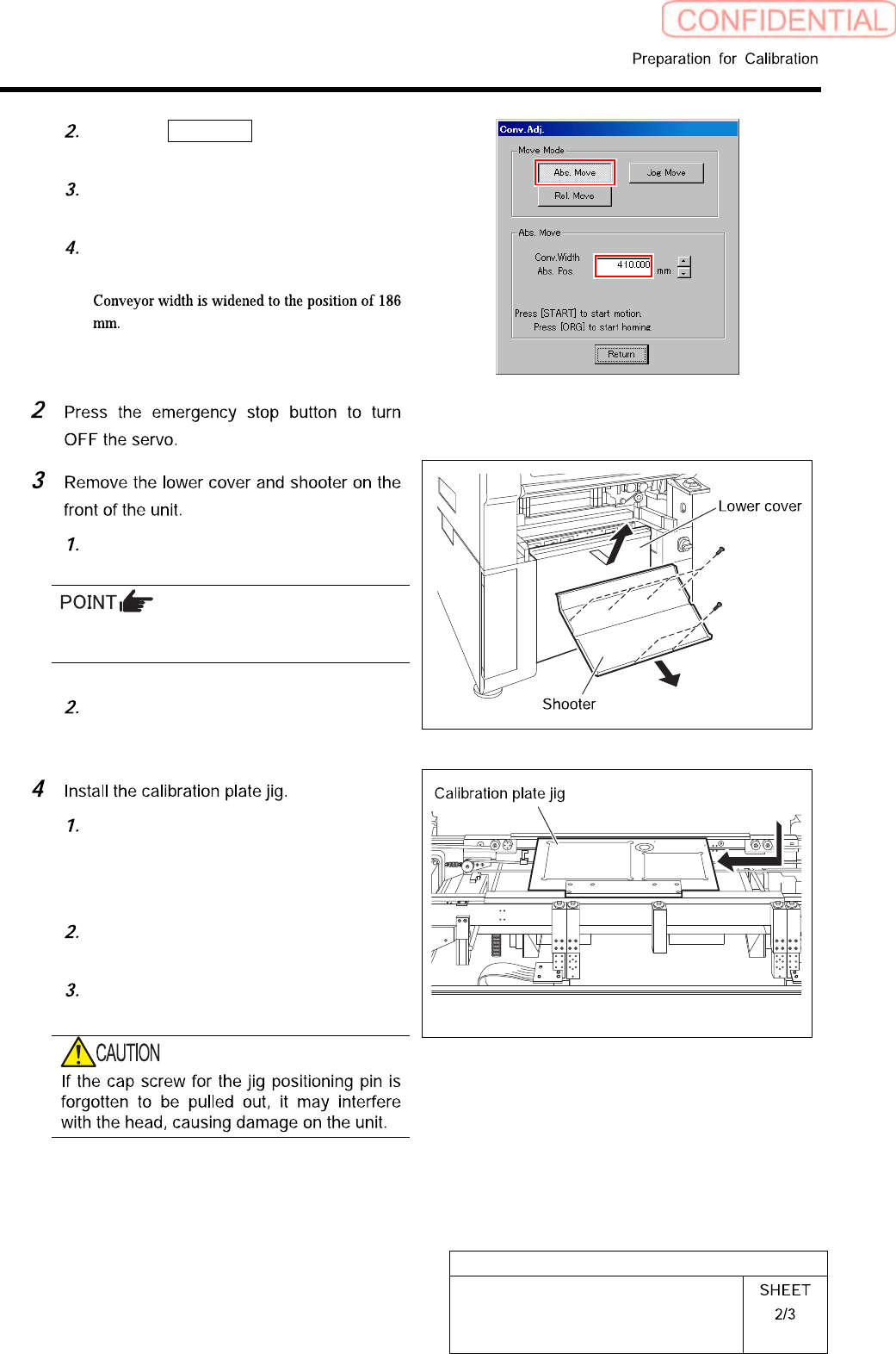
Click the Abs. Move button on the
Conv. Adj. screen.
Input “186” into the input box of the
Conv. Width Abs. Pos.
Press the [START] button on the
operation panel.
Loosen screw (2-+T4x8) to remove the
lower cover.
Tile the lower cover slightly toward you and
pull the fan cable to remove the lower panel.
Loosen screw (2-+T4x8) to remove the
shooter.
Place the calibration plate jig on the
rail on the right of the conveyor and
slide it to near the center of the
conveyor.
Insert the jig positioning pins (two)
into the calibration plate jig.
Remove the cap screw for jig
positioning pin.