MAN00000772_SI-G200BB_SVCPDFA.pdf - 第159页
HLGB-10103-01 Front, Rear LED Control PWB Setup Setup of LED control board used for SI-G2 0 0BB will be explained. Check this setup for the fro nt and rear head respectively . [Procedure] Remove the shooter on the rear o…
HLGB-10102-01
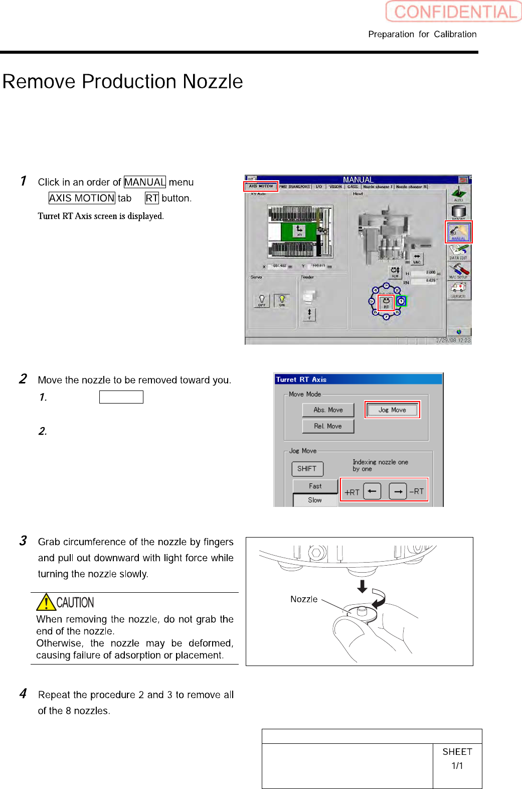
Remove Production Nozzle
Remove the nozzle used for production according to the procedure in this section because it is not
used for calibration operation.
[Procedure]
Click the Jog Move button in the move
mode.
Press the cursor key on the left and
right to jog move the nozzle to be
removed toward you.
HLGB-10103-01
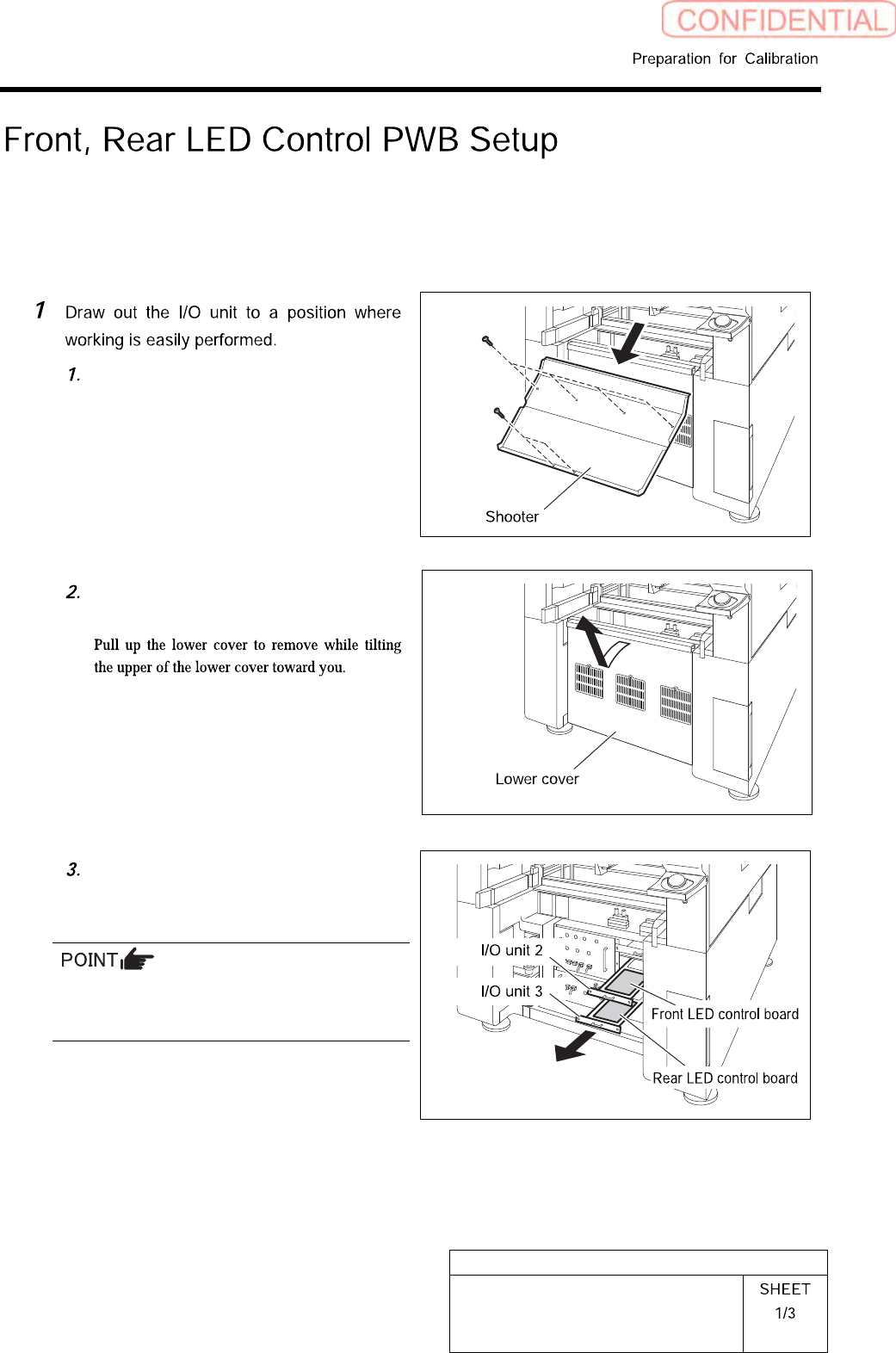
Front, Rear LED Control PWB Setup
Setup of LED control board used for SI-G200BB will be explained. Check this setup for the front and
rear head respectively.
[Procedure]
Remove the shooter on the rear of the
unit.
Remove the lower cover on the rear of
the unit.
Loosen two screws to draw out the I/O
unit 2 and I/O unit 3.
The front LED control board is stored in the I/O
unit 2, and the rear LED control board is stored
in the I/O unit 3.
HLGB-10103-01
Front, Rear LED Control PWB Setup
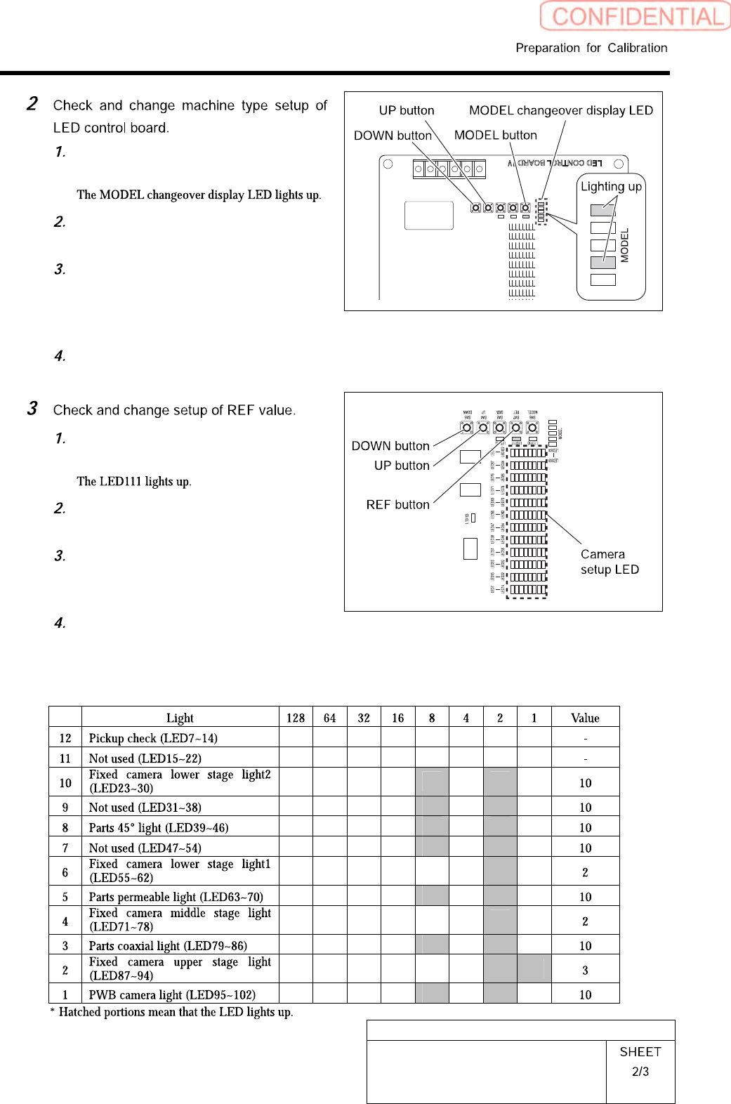
Press the MODEL button for three
seconds or longer.
Check that the LEDs light up at the
position shown in the Fig.
If the LED lighting-up state is
different, press the UP/DOWN switch
to change the lighting LED as shown
in the Fig.
When ending setup, wait until the
LED lights off.
Press the REF button for three
seconds or longer.
Press the REF button to select light to
be set up.
To change the setting, press the
UP/DOWN button to change so that
the camera setup LED lights up.
When ending setup, wait until the
LED lights off.
SI-G200BB
headREFvaluesetuplist