MAN00000772_SI-G200BB_SVCPDFA.pdf - 第190页
HLGB-10206-01 F A xis Setup Click the Jog Move button. Press the cursor key to move the feed part onto the feed adjust ing jig. Place the part feed height jig (1 10.4mm) on the feed adjusting ji g. Adjust position so tha…
HLGB-10206-01
F Axis Setup
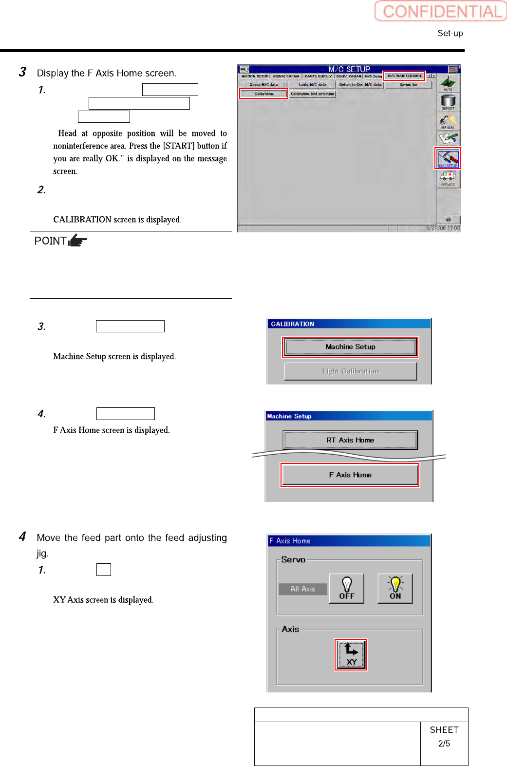
Click in an order of M/C SETUP
menuM/C MAINTENANCE
tabCalibration button.
“
Press the [START] button on the
operation panel.
For procedures when selecting head for which
calibration is performed, and when changing
calibration jig, refer to the “How to display
calibration screen (HLGB-10105-01)”.
Click the Machine Setup button on the
CALIBRATION screen.
Click the F Axis Home button.
Click the XY button on the F Axis
Home screen.
HLGB-10206-01
F Axis Setup
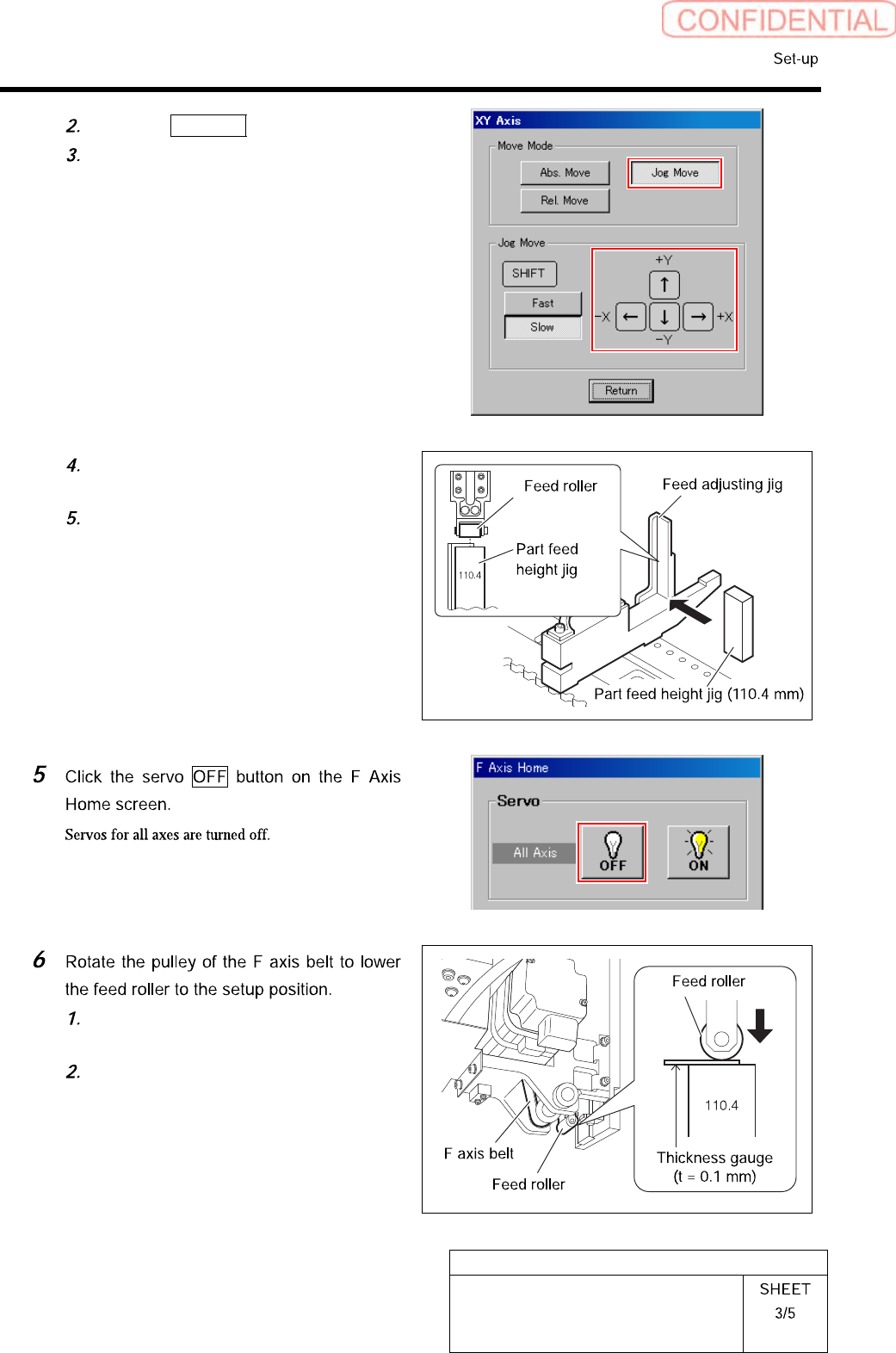
Click the Jog Move button.
Press the cursor key to move the feed
part onto the feed adjusting jig.
Place the part feed height jig
(110.4mm) on the feed adjusting jig.
Adjust position so that center of the
feed roller is on the center of the part
feed height jig.
Pinch a thickness gauge of 0.1mm on
the part feed height jig.
Rotate the pulley of the F axis belt to
lower the feed roller to a position
where it contacts the thickness gauge.
HLGB-10206-01
F Axis Setup
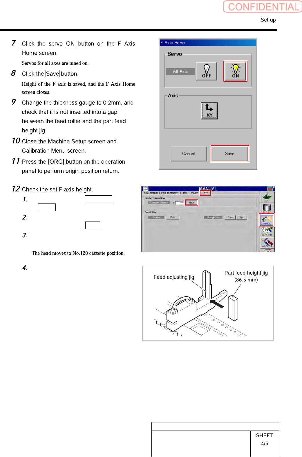
Click in an order of MANUAL menu
CASS. tab.
Input “120” into the cassette position
space, and click the Move.
Press the [START] button on the
operation panel.
Replace the parts feed height jig
(110.4mm) on the feed adjustment jig
with a parts feed height jig of 86.5mm.