MAN00000772_SI-G200BB_SVCPDFA.pdf - 第197页
HLGB-10208-01 Pickup Check Camera Setup Perform this working on b o th he ads on t he front side and rear side. [Necessary jigs] • Length reference nozzle jig • Scale (about 150 mm) [Position adjustment for rise end stop…
HLGB-10207-01
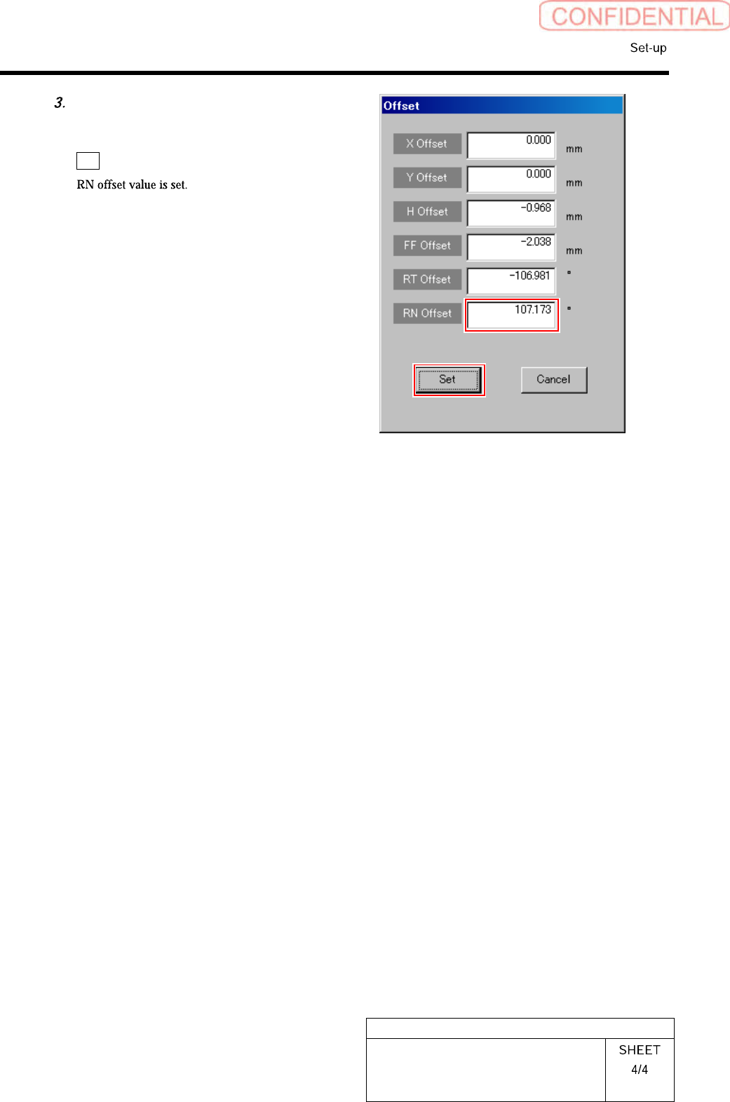
RN Axis Origin Offset Setup
Input the value (example: 110.1)
obtained in the previous procedure
into the RN Offset box, and click the
Set button.
HLGB-10208-01
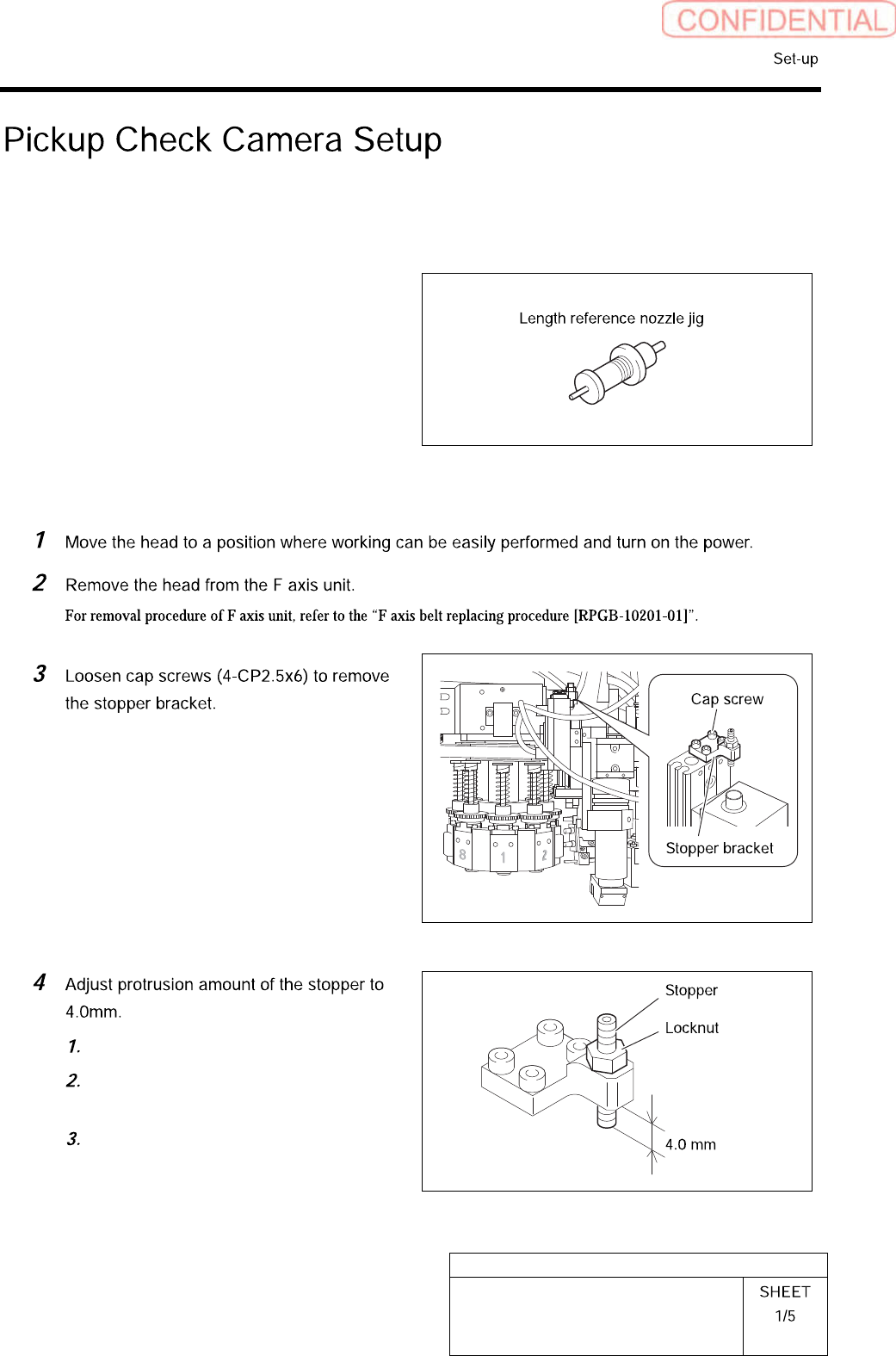
Pickup Check Camera Setup
Perform this working on both heads on the front side and rear side.
[Necessary jigs]
• Length reference nozzle jig
• Scale (about 150 mm)
[Position adjustment for rise end stopper]
Loosen the locknut.
Adjust protrusion amount of the
stopper to 4.0mm.
Tighten the locknut.
HLGB-10208-01
Pickup Check Camera Setup
×
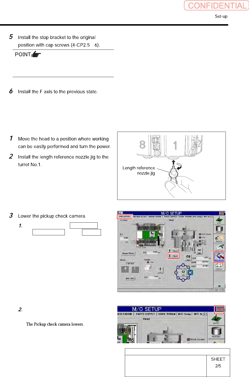
Before tightening cap screws (4-CP2.5×6),
apply small amount of adhesive “1401B” of
THREE BOND to prevent looseness.
[Position adjustment for lowering end stopper]
Click in an order of M/C SETUP menu
ORG OFFSET tab ↓Check
button.
Press the arrow mark on the right
upper section of the screen.