MAN00000772_SI-G200BB_SVCPDFA.pdf - 第212页
HLGB-10304-01 Auto Calibration (Recognition of relationship betw een PW B coordinate and mechanism coordinate) Press the power off switch. T urn off the main breaker . Remove th e Lower cover and the shooter fr…
HLGB-10304-01
Auto Calibration
(Recognition of
relationship between PWB coordinate and
mechanism coordinate)
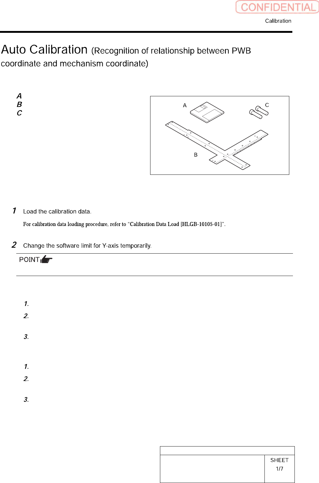
[Necessary jigs]
Calibration data FD
Ball point jig
Positioning pins for ball point jig
[Procedure]
Make sure to take a note of the original value before changing it.
<To execute calibration with the front head>
Open “c:¥asm¥mcdata1¥ac_param.ini” with WordPad.
Add the absolute value 100 to “SOFT_LIMIT_PLUS” and “SOFT_LIMIT_MINUS” of
[AC_Y] respectively.
Save (overwrite) the file, and then restart the system.
<To execute calibration with the rear head>
Open “c:¥asm¥mcdata2¥ac_param.ini” with WordPad.
Add the absolute value 100 to “SOFT_LIMIT_PLUS” and “SOFT_LIMIT_MINUS” of
[AC_Y] respectively.
Save (overwrite) the file, and then restart the system.
HLGB-10304-01
Auto Calibration
(Recognition of
relationship between PWB coordinate and
mechanism coordinate)
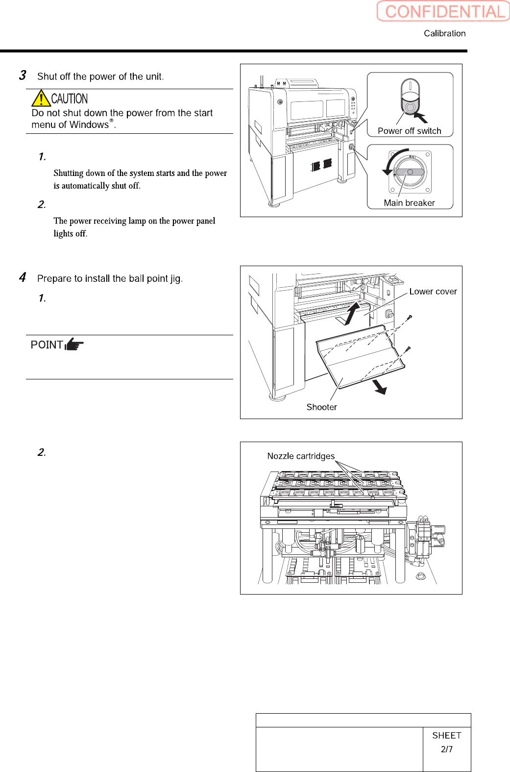
Press the power off switch.
Turn off the main breaker.
Remove the Lower cover and the
shooter from the front and rear side of
the unit.
Tile the lower cover slightly toward you and pull
the fan cable to remove the lower panel.
Remove all the nozzle cartridges from
the rear side of the unit.
HLGB-10304-01
Auto Calibration
(Recognition of
relationship between PWB coordinate and
mechanism coordinate)
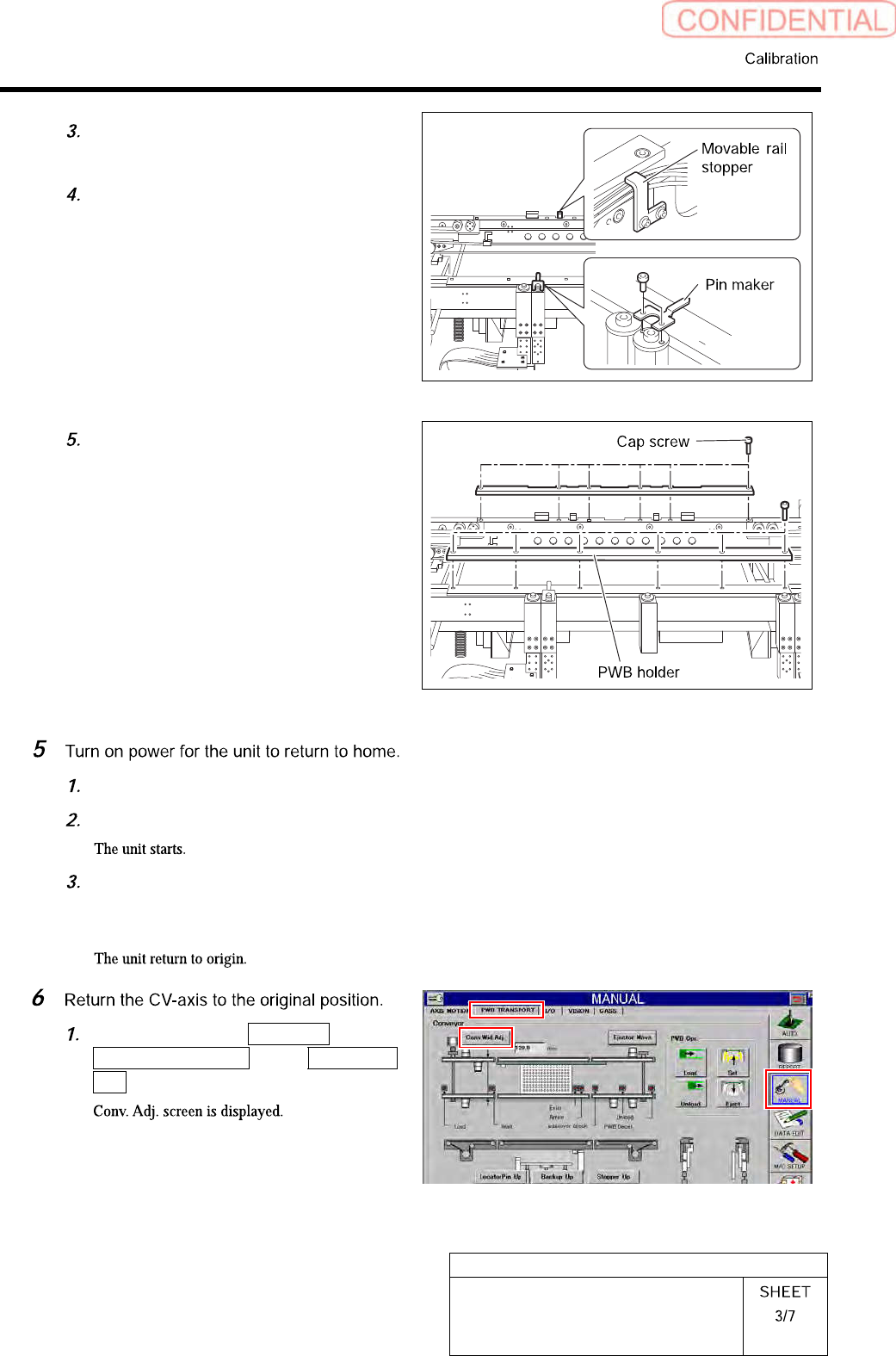
Loosen cap screws (CP4x6) to remove
the pin marker.
Loosen cap screws (2-CP4x10) to
remove the movable rail stopper.
Unscrew the cap screw (12-CP4x10) to
remove the PWB holder installed on
the conveyer.
Turn OFF the main breaker.
Press the power on switch.
Press the [ORG] button on the
operation panel with the HI screen
being displayed.
Click in an order of MANUAL menu
PWB TRANSPORT tab Conv. Wid.
Adj. button.