MAN00000772_SI-G200BB_SVCPDFA.pdf - 第219页
HLGB-10305-01 Auto Calibration (Recognition of Relationship between th e Fixed Camera and Nozzle) Click in an ord er of MANUAL menu AXIS MOTION tab XY button. Click the Jog Move button in the mo ve mode. Install the …
HLGB-10305-01
Auto Calibration
(Recognition of
Relationship between the Fixed Camera
and Nozzle)
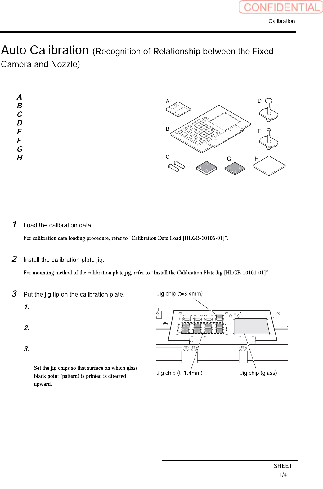
[Necessary jigs]
Calibration data FD
Calibration plate jig
Positioning pins for calibration plate
BF00900 nozzle (1 pc.)
BF60400 nozzle (7 pcs.)
Calibration jig chip (t=3.4, 1 pc.)
Calibration jig chip (t=1.4, 8 pcs.)
Calibration jig chip (glass)
[Procedure]
Put 8 thinner jig chips (t=1.4mm) to
front side.
Put thicker jig chip (t=3.4mm) to the
right end of the deep row.
Put jig chip (glass) on the right
countersunk section.
HLGB-10305-01
Auto Calibration
(Recognition of
Relationship between the Fixed Camera
and Nozzle)
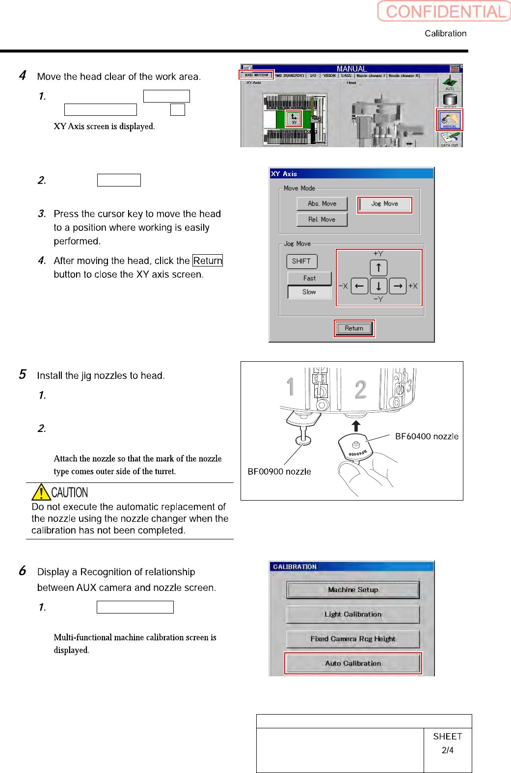
Click in an order of MANUAL menu
AXIS MOTION tab XY button.
Click the Jog Move button in the move
mode.
Install the BF00900 nozzles (1 piece)
to the turrets No.1.
Install the BF60400 nozzles (7 pieces)
to the turrets No.2~8.
Click the Auto Calibration button on
the CALIBRATION screen.
HLGB-10305-01
Auto Calibration
(Recognition of
Relationship between the Fixed Camera
and Nozzle)
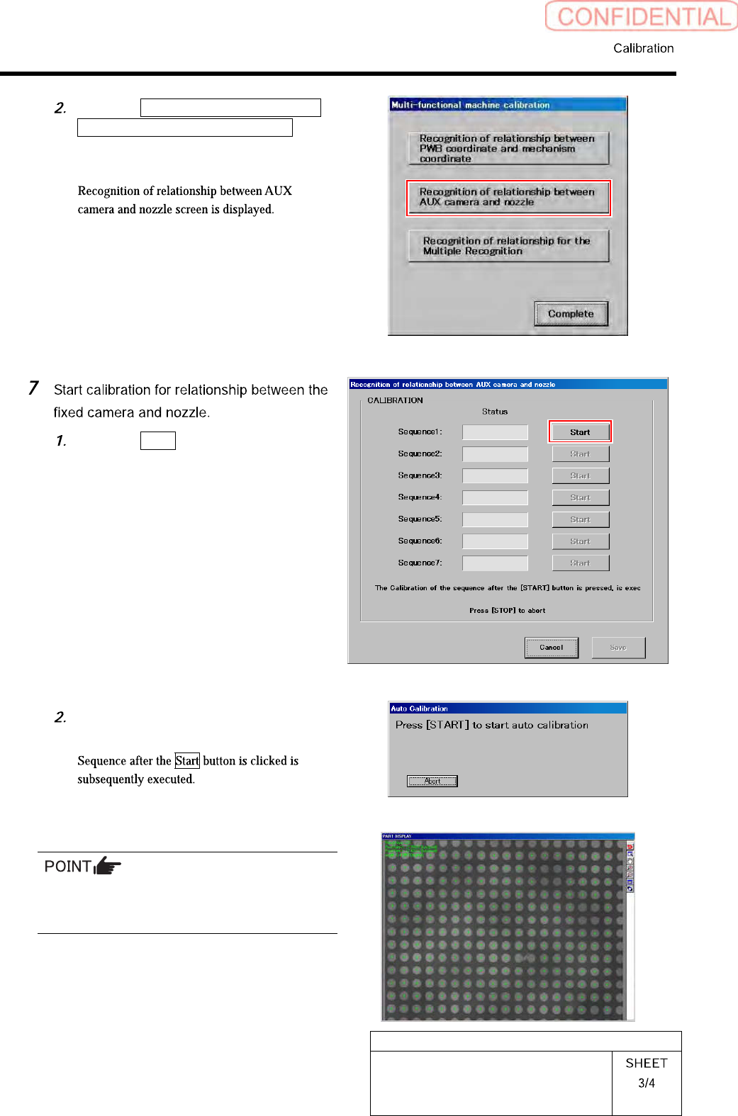
Click the Recognition of relationship
between AUX camera and nozzle
button on the Multi-functional
machine calibration screen.
Click the Start button of Sequence 1.
Press the [START] button to start the
auto calibration.
In a process of recognizing a large glass PWB,
some portion of PWB may not be recognized.
Even so, keep on the operation.