MAN00000772_SI-G200BB_SVCPDFA.pdf - 第248页
HLGB-1031 1- 01 Pickup Position Setup [XY Position Data T eaching] Click the ON button on th e PWB camera light. Set brightness of the PW B camera light to “6” or “7”. Click the Move button. Click the Set the crosshair t…
HLGB-10311-01
Pickup Position Setup
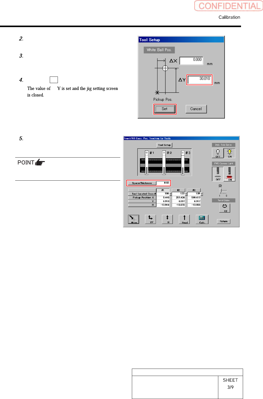
Check jig information (ΔY) attached
on the side of the pickup point jig.
Enter value ofΔY written on the side
of the pickup point jig into the ΔY box
on the jig setting screen.
Click the Set button.
Δ
Input thickness of “0.03” of thickness
gauge used for H axis position data
teaching.
The value of the spacer thickness becomes
offset value when acquiring H coordinate.
HLGB-10311-01
Pickup Position Setup
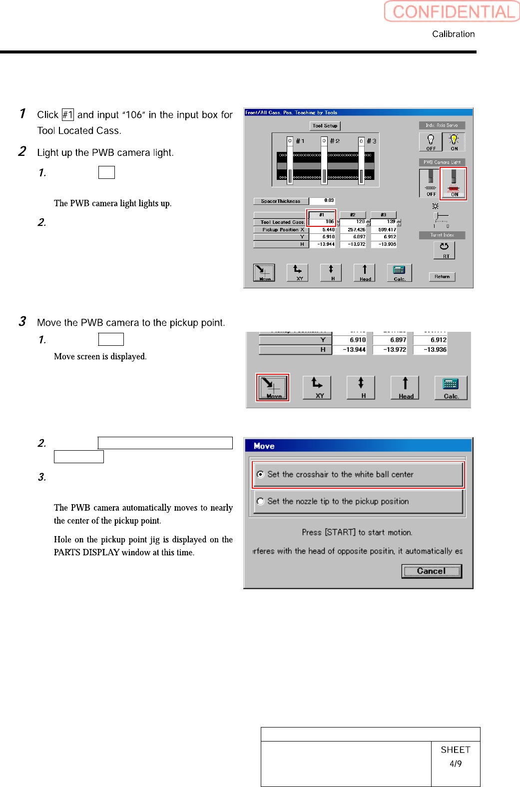
[XY Position Data Teaching]
Click the ON button on the PWB
camera light.
Set brightness of the PWB camera
light to “6” or “7”.
Click the Move button.
Click the Set the crosshair to the white
ball center button.
Press the [START] button on the
operation panel.
HLGB-10311-01
Pickup Position Setup
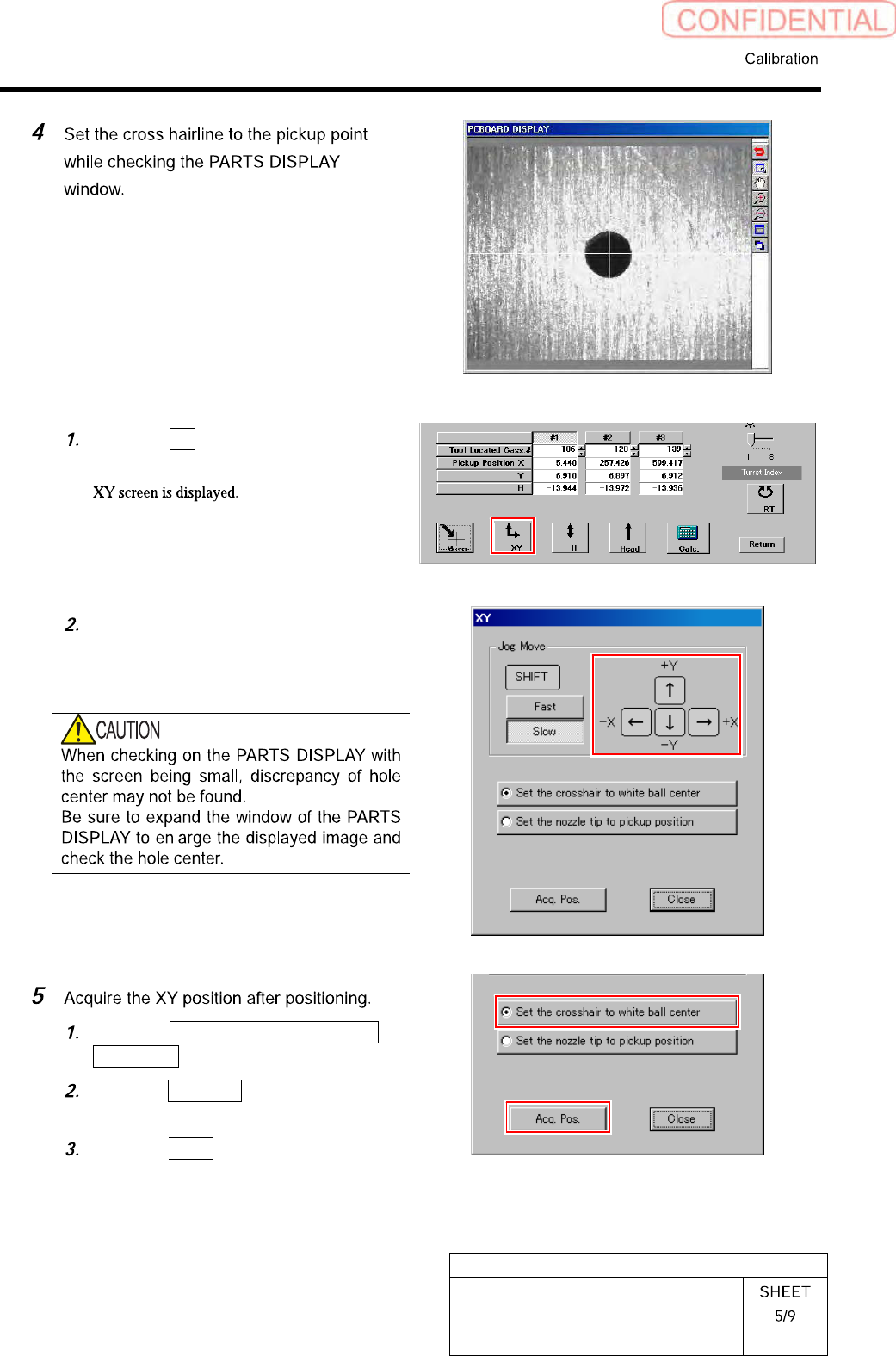
Click the XY button on the Front/All
Cass. Pos. Teaching by Tools screen.
Press the cursor key to jog move the
head until the hole in the end of the
pickup point jig is positioned on the
crosshair on the PARTS DISPLAY.
Click the Set the crosshair to white
ball center button.
Click the Acq. Pos. button on the XY
screen to acquire XY position.
Click the Close button to close the XY
screen.