MAN00000772_SI-G200BB_SVCPDFA.pdf - 第250页
HLGB-1031 1- 01 Pickup Position Setup
HLGB-10311-01
Pickup Position Setup
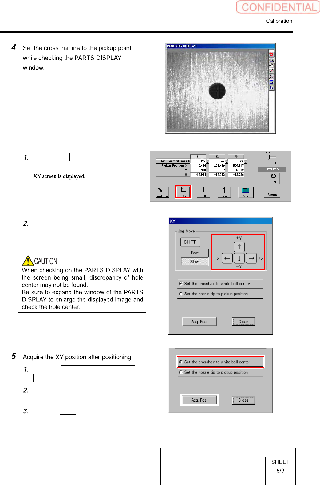
Click the XY button on the Front/All
Cass. Pos. Teaching by Tools screen.
Press the cursor key to jog move the
head until the hole in the end of the
pickup point jig is positioned on the
crosshair on the PARTS DISPLAY.
Click the Set the crosshair to white
ball center button.
Click the Acq. Pos. button on the XY
screen to acquire XY position.
Click the Close button to close the XY
screen.
HLGB-10311-01
Pickup Position Setup
HLGB-10311-01
Pickup Position Setup
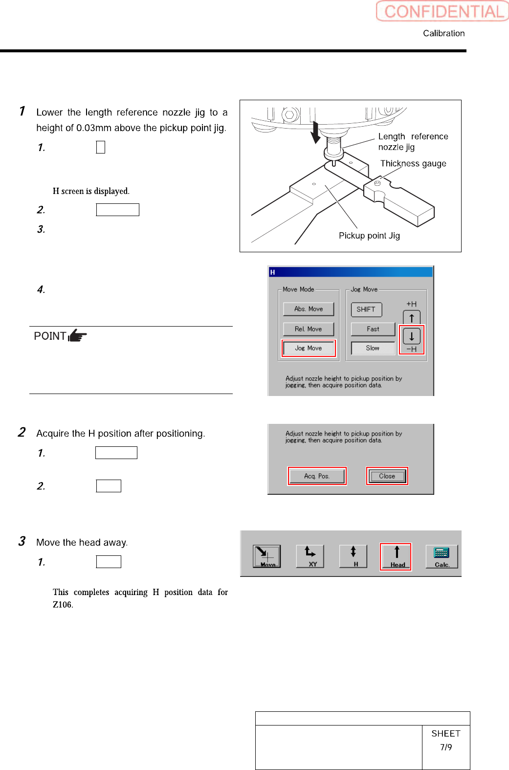
[H Position Data Teaching]
Click the H button on the front and
cassette position whole teaching
screen.
Click the Jog Move button.
Press the downward cursor key to
lower the H axis until the gap between
the length reference nozzle jig and
pickup point jig becomes 0.03mm.
Check that thickness gauge of 0.03mm
is inserted into the gap, and thickness
gauge of 0.04mm is not inserted.
・ Use a thickness gauge with the same
thickness as the “spacer thickness” input in
the Front/All Cass. Pos. Teaching by Tools
screen.
Click the Acq. Pos. button on the H
screen to acquire H position of Z106.
Click the Close button to close H
screen.
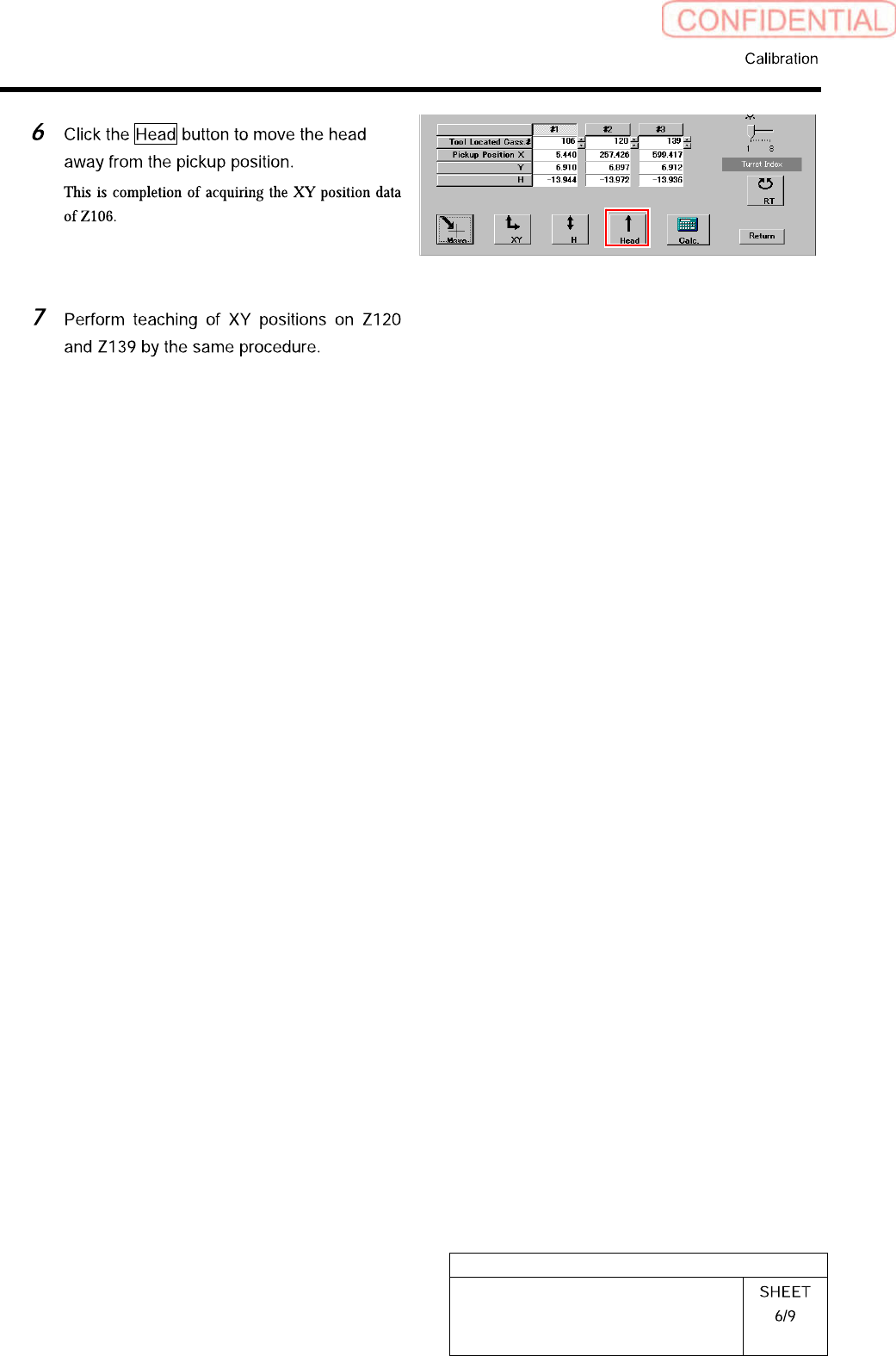
Click the Head button to move the
head away from the pickup position.