MAN00000772_SI-G200BB_SVCPDFA.pdf - 第254页
HLGB-10312-01 Checking Pickup Position Check pickup pos itions at three l ocations of cassette tables (Z101 、 Z120 、 Z1 40) on the front side, and three locations of cassette tabl es (Z101 、 Z120 、 Z140) on the rear side…
HLGB-10311-01
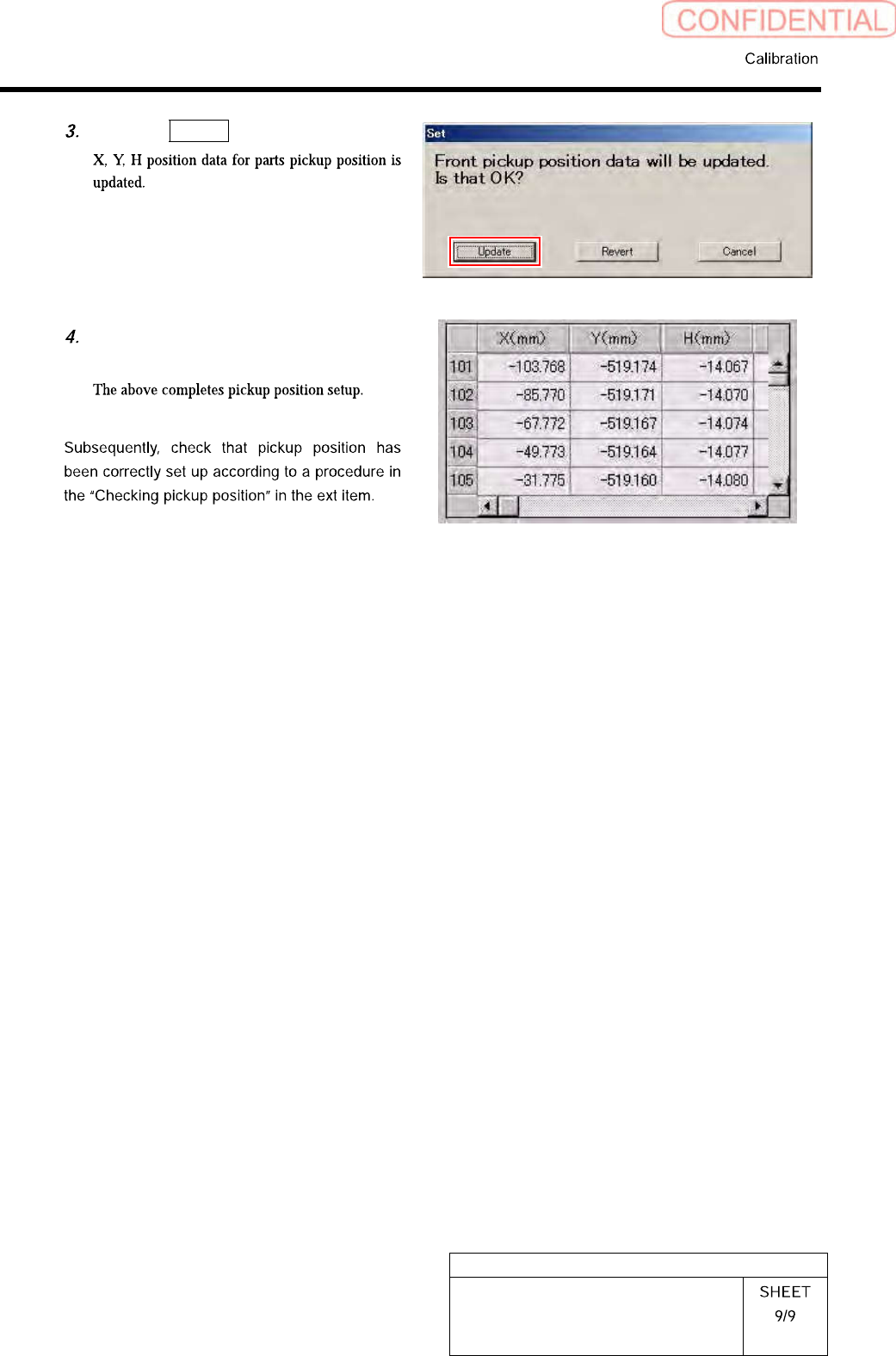
Pickup Position Setup
Click the Update button.
Check that the front position data
value was updated.
HLGB-10312-01
Checking Pickup Position
Check pickup positions at three locations of cassette tables (Z101、Z120、Z140) on the front side, and
three locations of cassette tables (Z101、Z120、Z140) on the rear side.
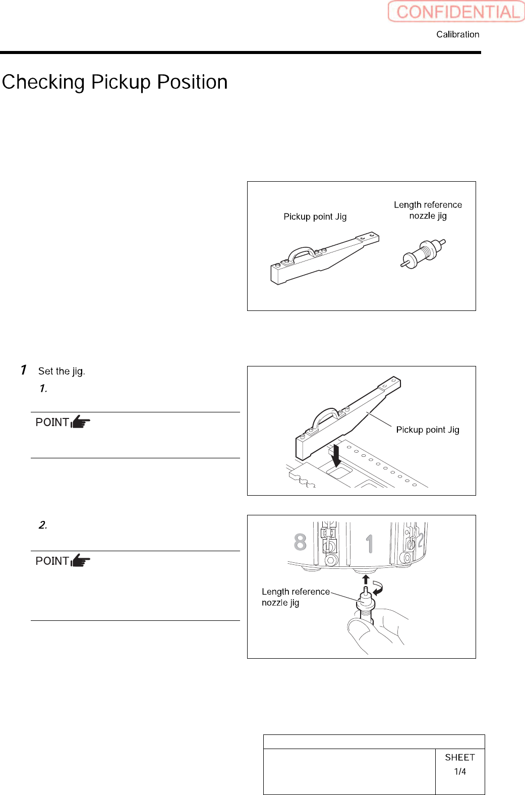
[Necessary jigs]
• Pickup point Jig
• Length reference nozzle jig
[Procedure]
Set pickup point jig to Z101 on the
cassette table.
There should be no gap between the feed
adjusting jig and the cassette table.
Install the length reference nozzle jig
to the turret No.1.
When installing the nozzle, insert it while
slowly turning.
After inserting the nozzle, check that it is not
drawn out by pulling downward.
HLGB-10312-01
Checking Pickup Position
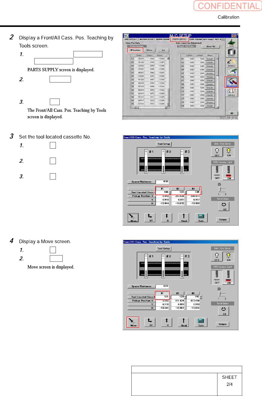
Click in an order of M/C SETUP menu
PARTS SUPPLY tab.
Click the Teaching button on the Front
Pos. Data to display a drop down
menu.
Click the Jigs in the drop down menu.
Click the #1 and input “101” in input
box for Tool Located Cass.
Click the #2 and enter “120” in the
input box for Tool Located Cass.
Click the #3 and input “140” in input
box for Tool Located Cass.
Click the #1.
Click the Move button.