MAN00000772_SI-G200BB_SVCPDFA.pdf - 第287页
HLGB-10401-01 Matching of X Axis Z-Phase This section describes a procedu re to adjust a posi tio n of the Z-Phase so that the motor stops at a position (Z-Phase sett ing position) where the ORG sensor detects the dog, t…
HLGB-10317-01
Parts Discard Position Adjustment
Perform this working on both heads on the front side and rear side.
[Procedure]
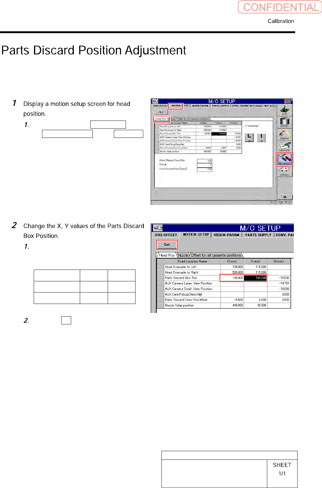
Click in an order of M/C SETUP menu
MOTION SETUP tab Head Pos.
tab.
Input the following values into the
setting space of the Parts Discard Box
Position.
X Y
FrontsidePC -60.0 160.0
RearsidePC 60.0 -180.0
Click the Set button.
HLGB-10401-01
Matching of X Axis Z-Phase
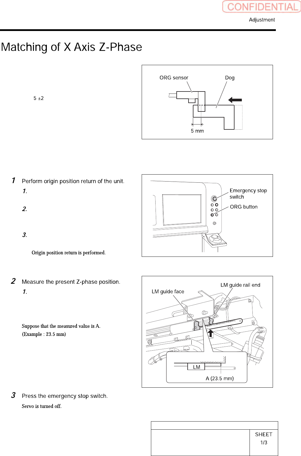
This section describes a procedure to adjust a position
of the Z-Phase so that the motor stops at a position
(Z-Phase setting position) where the ORG sensor
detects the dog, then moves to the X-CCW sensor side
(left side) by mm when origin return is performed,
by taking X axis on the front head side as an example.
Also match the Z-Phase for the X axis of the rear head
side by the same procedure.
[Procedure]
Close the front and rear doors in order
to prevent danger.
Prepare to press the emergency stop
switch so as to immediately stop the
unit.
Press the [ORG] button on the
operation panel.
Measure the distance from the LM
guide rail end to the LM guide face on
the left side of the unit with a scale.
HLGB-10401-01
Matching of X Axis Z-Phase
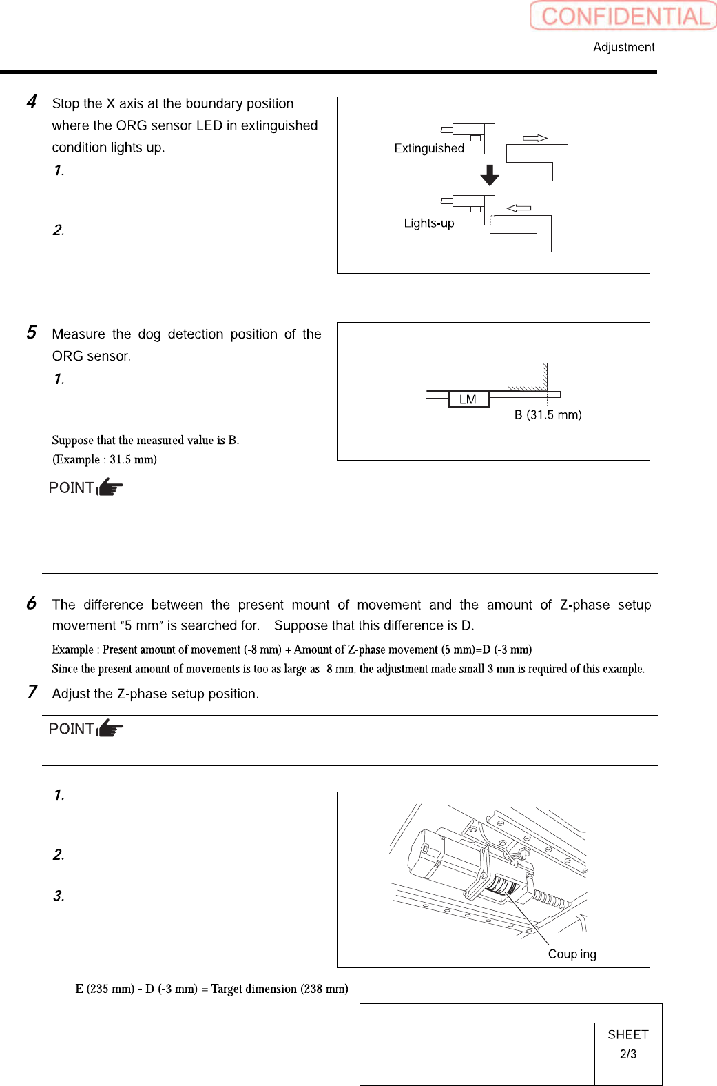
Manually move the X axis in right
direction to the position where the dog
leaves the ORG sensor.
Manually move the X axis in left
direction little by little and stop at the
boundary position where the ORG
sensor LED in extinguished condition
lights up.
Measure the distance from the frame
end face to the LM guide face on the
left side of the unit with a scale.
By 2 times of measurements, the amount of movements from the dog detection position of an ORG sensor
to the present Z-phase position can be found.
Suppose that the present amount of movement is C.
Example : A (23.5 mm) - B (31.5 mm) = C (-8 mm)
Adjust the Z-phase setup position by adjusting the positional relation between the motor and ball screw.
Move the head to the center of X axis
to secure working space to loosen the
coupling screws.
Loosen the screw M4 on the ball screw
side of the coupling.
Measure the distance from the LM
guide rail end to the LM guide face
with a scale. (Example : 235 mm)
Suppose that this measured value is E.