MAN00000772_SI-G200BB_SVCPDFA.pdf - 第296页
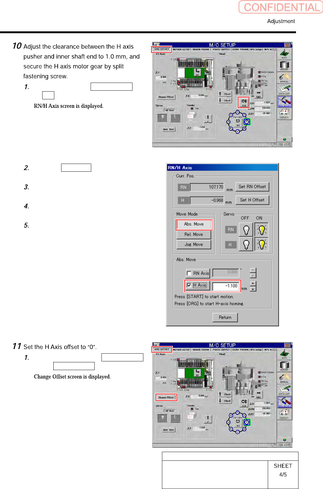
HLGB-10403-01 H A xis Gear Z-phase Matching Click in an order of ORG O F FSET tab R.H button. Click the Abs. Move button in the move mode. Click the check box for H axi s an d put check in it to input “-1.1”. Press the…
HLGB-10403-01
H Axis Gear Z-phase Matching
Close the explorer window.
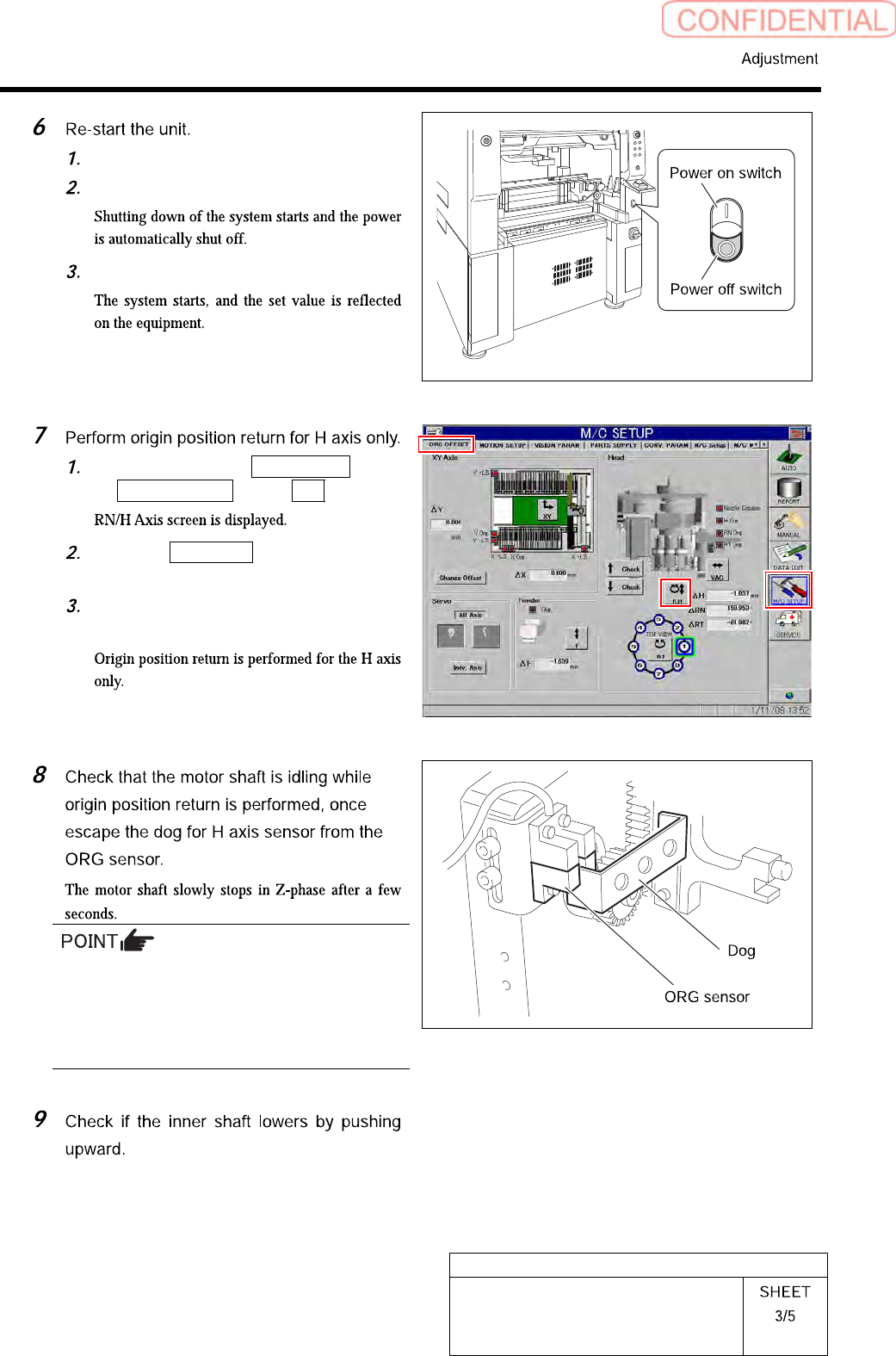
Press the power off switch.
Press the power on switch.
Click in an order of M/C SETUP menu
ORG OFFSET tab R.H button.
Click the Abs. Move button for move
mode and put checkmark on H axis.
Press the [ORG] button on the
operation panel.
Unless the gear is free against the motor shaft
of the H axis, the dog obstructs the CCW sensor
and the servo is turned off.
Check that the gear is completely free against
the motor shaft of the H axis.
HLGB-10403-01
H Axis Gear Z-phase Matching
Click in an order of ORG OFFSET tab
R.H button.
Click the Abs. Move button in the
move mode.
Click the check box for H axis and put
check in it to input “-1.1”.
Press the [START] button on the
operation panel.
Tighten the split fastening screw for
the H axis motor gear.
Click in an order of the ORG OFFSET
tab Change Offset button.
HLGB-10403-01
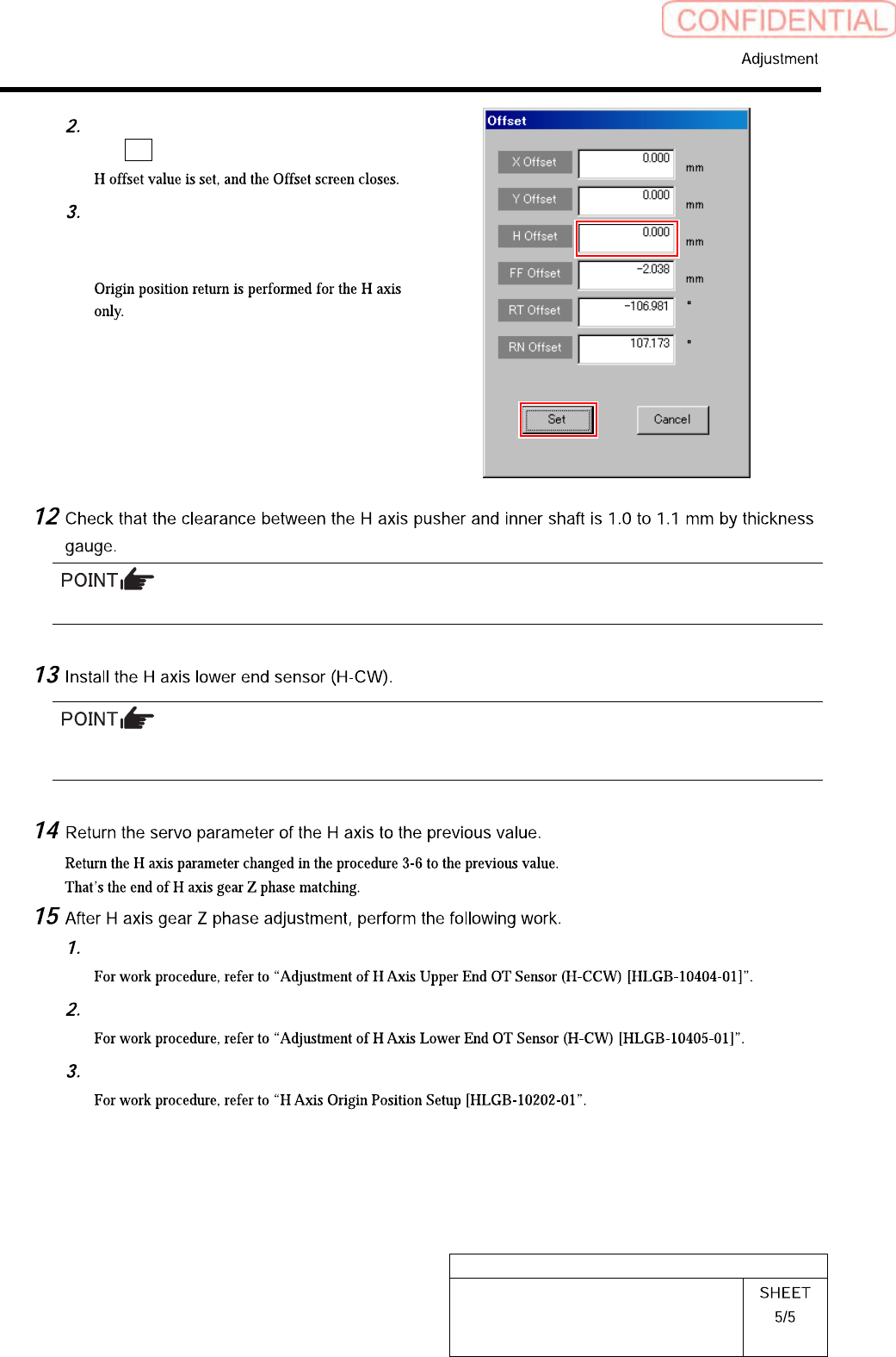
H Axis Gear Z-phase Matching
Input “0” in the H Offset box, and click
the Set button.
Press the [ORG] button on the
operation panel with the RN/H axis
screen displayed.
Unless the clearance is 1.0 to 1.1 mm, it is necessary to re-perform “H axis origin position setup”.
Perform position adjustment of the lower end sensor (H-CW) in the post-process of “Adjustment H axis
lower end OT sensor (H-CW)”.
Adjust OT sensor at the upper end of H axis.
Adjust OT sensor at the lower end of H axis.
Set H axis origin position.