MAN00000772_SI-G200BB_SVCPDFA.pdf - 第315页
HLGB-10410-01 Gap A djustment for Head Unit Mechanical V alve and Plunger [Gap adjusting procedure] Loosen the cap screws (4 pcs, C3 x 5). Adjust the gap between th e end of the retracted plunger and the end of the proje…
HLGB-10410-01
Gap Adjustment for Head Unit
Mechanical Valve and Plunger
Because working has to be performed from the rear side of the head part, work on the head on the front
side from the rear of the unit, and the head on the rear side from the front of the unit.
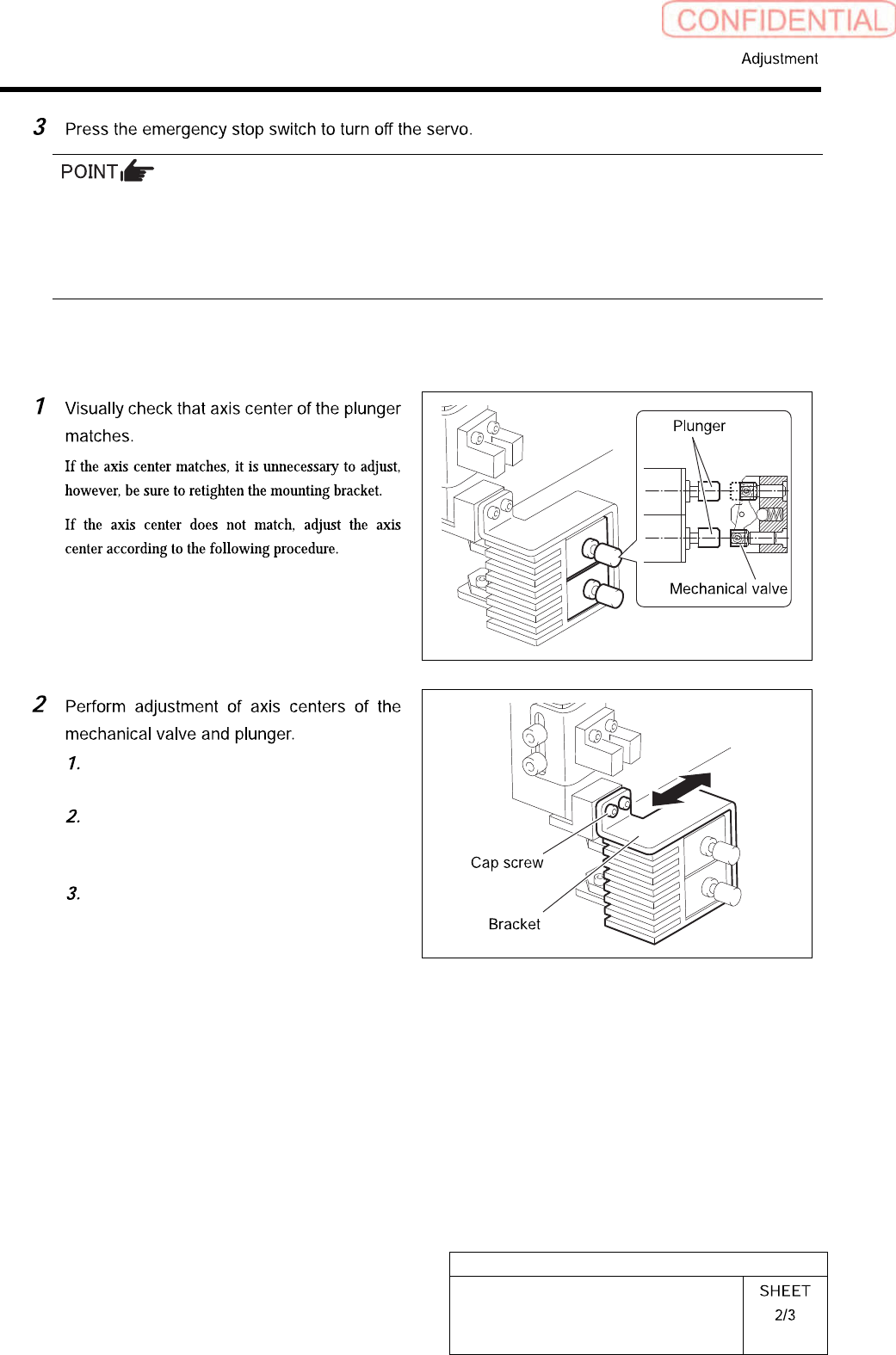
Press the emergency stop switch on the working side to turn OFF the servo in order to prevent the unit
from being operated mistakenly from opposite side of the unit without noticing that the other worker is
working.
[Axis center adjuting procedure]
Loosen the cap screws (2 pcs, C3 x 6)
on the mounting bracket for plunger.
Move the bracket back and forth to
match the axis centers of the
mechanical valve and the plunger.
While matching the axis center in
height direction, fasten the cap screws
(2 pcs, C3 x 6) to fix the bracket.
HLGB-10410-01
Gap Adjustment for Head Unit
Mechanical Valve and Plunger
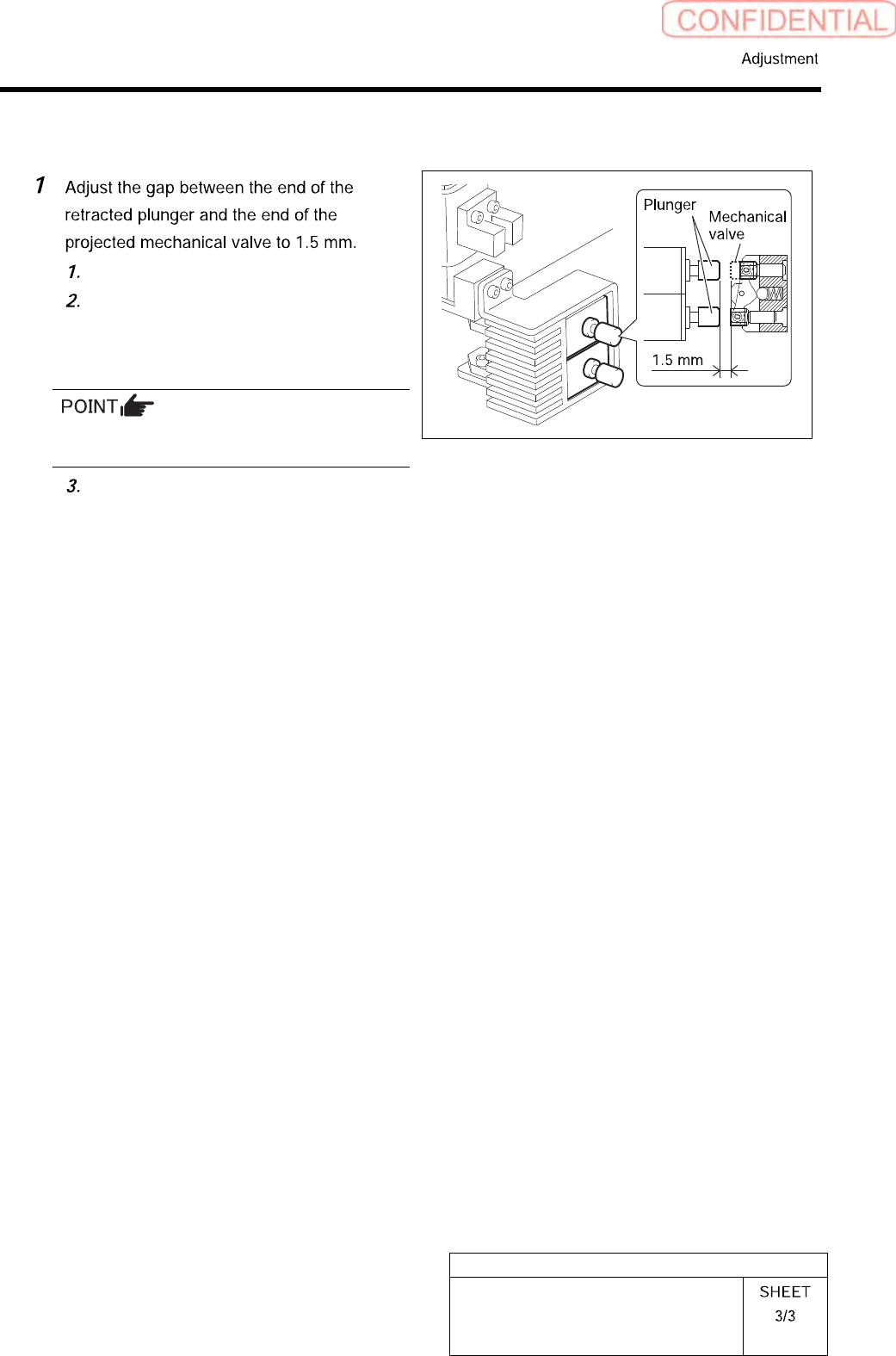
[Gap adjusting procedure]
Loosen the cap screws (4 pcs, C3 x 5).
Adjust the gap between the end of the
retracted plunger and the end of the
projected mechanical valve to 1.5 mm
using a thickness gauge.
The mechanical valve and the plunger head
should be parallel to each other.
While matching the axis center in
height direction, fasten the cap screws
(4 pcs, C3 x 5) to fix the plunger.
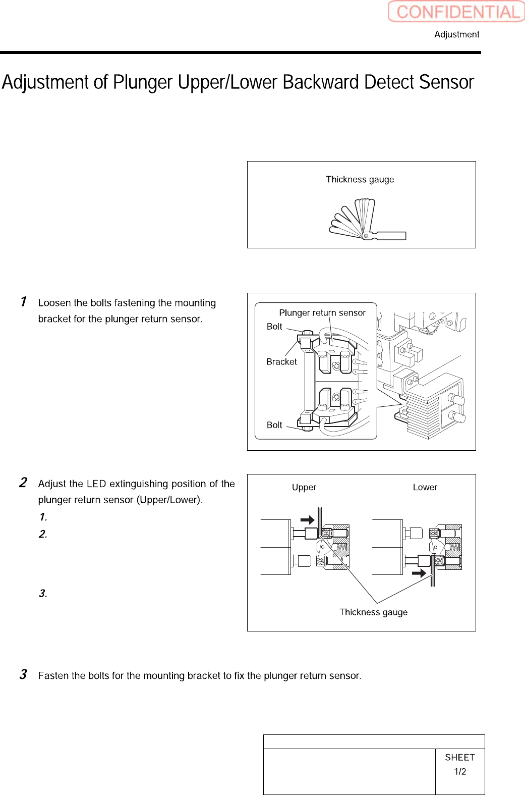
HLGB-10411-01
Adjustment of Plunger Upper/Lower
Backward Detect Sensor
Perform this working on both heads on the front side and rear side.
[Necessary jigs]
• Thickness gauge
[Procedure]
Press in the mechanical valve.
Pull out the plunger by hand, and
pinch a thickness gauge of t=1.0 mm
between the plunger and mechanical
valve.
Move the bracket to adjust the sensor
position so that the LED for the
plunger return sensor extinguishes in
this state.