MAN00000772_SI-G200BB_SVCPDFA.pdf - 第317页
HLGB-1041 1- 01 Adjustment of Plunger Upper/Lower Backward Detect Sensor Press in the mechani cal valv e. Pull out the plung er by hand, and pinch a thickness g auge of t=1 .2 mm between the plunger and the mechanical va…
HLGB-10411-01
Adjustment of Plunger Upper/Lower
Backward Detect Sensor
Perform this working on both heads on the front side and rear side.
[Necessary jigs]
• Thickness gauge
[Procedure]
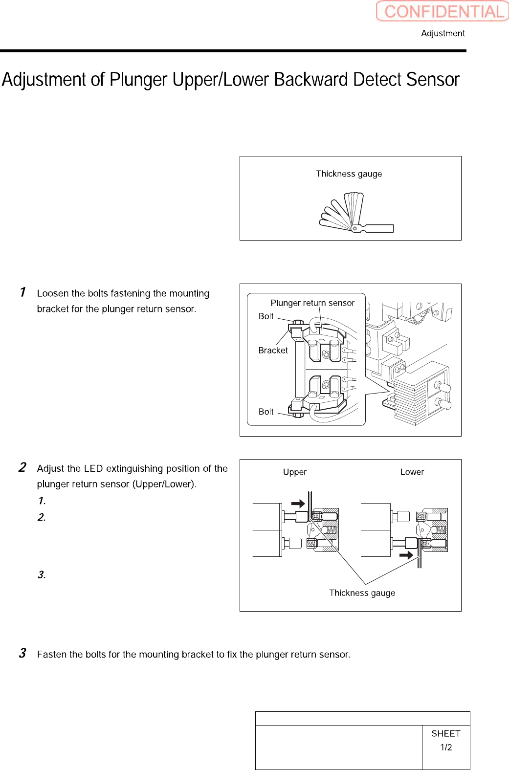
Press in the mechanical valve.
Pull out the plunger by hand, and
pinch a thickness gauge of t=1.0 mm
between the plunger and mechanical
valve.
Move the bracket to adjust the sensor
position so that the LED for the
plunger return sensor extinguishes in
this state.
HLGB-10411-01
Adjustment of Plunger Upper/Lower
Backward Detect Sensor
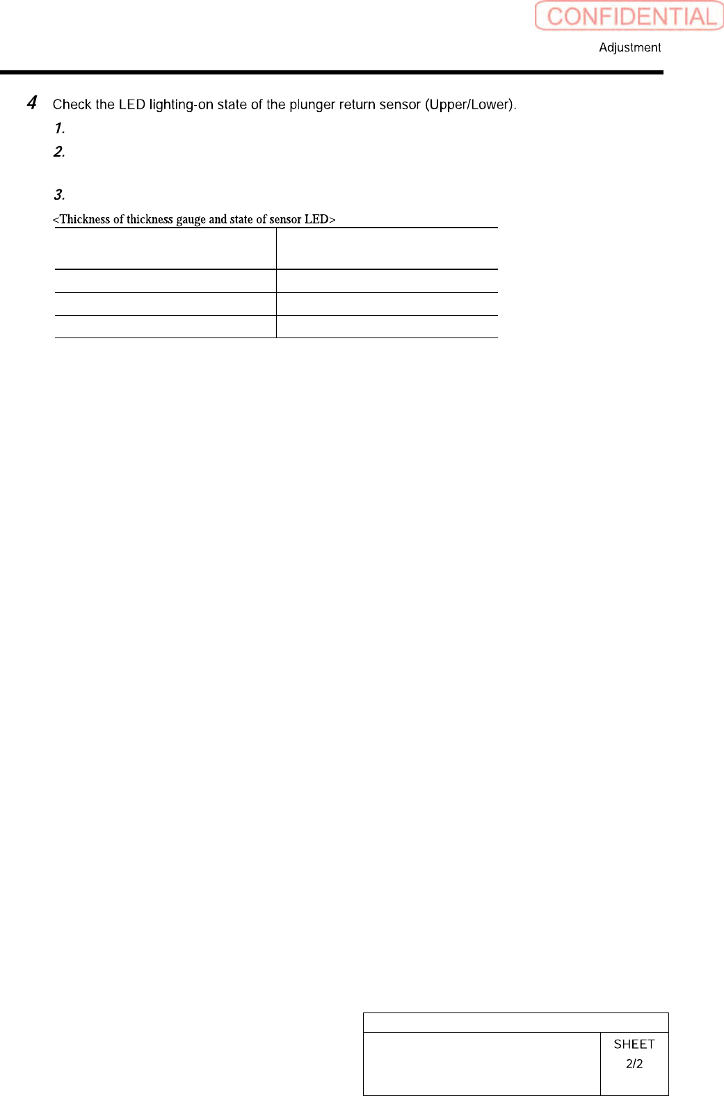
Press in the mechanical valve.
Pull out the plunger by hand, and pinch a thickness gauge of t=1.2 mm between the
plunger and the mechanical valve.
Check that the LED for the plunger return sensor lights up in this state.
Thickness of thickness gauge State of LED for plunger return
sensor
1.0 mm Extinguish
1.2 mm Lights-up
Non (Origin position) Lights-up
HLGB-10412-01
Nozzle Height Adjustment
Perform this working on both heads on the front side and rear side.
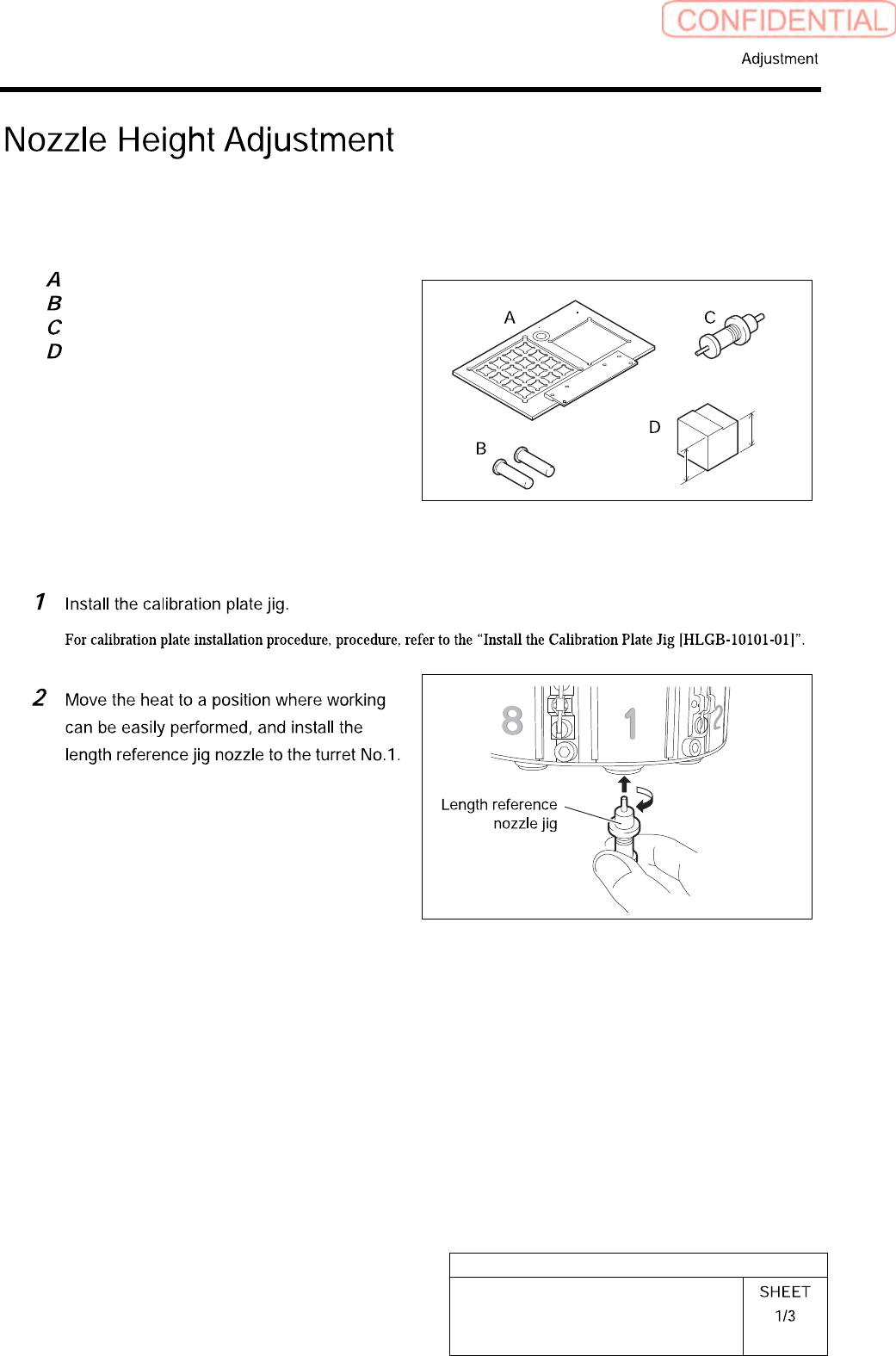
[Necessary jigs]
Calibration plate jig
Jig positioning pin
Length reference nozzle jig
Nozzle height adjusting block
23.1mm
22.9mm
[Procedure]