MAN00000772_SI-G200BB_SVCPDFA.pdf - 第333页
HLGB-10415-01 Nozzle Sensor A djustment [Necessary jigs] Jig nozzle for nozzle c hanger Nozzle (used in production) Scale (about 300 mm) [Adjust the sensor att achment height] Click in an ord er of MANUAL menu AXIS M O…
HLGB-10414-01
Phase Adjustment for Nozzle
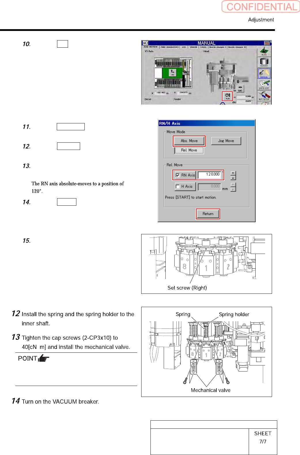
Click the R.H button on the AXIS
MOTION screen.
Click the Abs. Move button on the
RN/H-axis screen.
Click the RN-Axis button and input
“120” into the input space.
Press the [START] button on the
operation panel.
Click the Return button to close the
RN/H axis screen.
Tighten the sect screw (right) for the
small gear to 15[cN・m].
・
Tighten 2-CP3x10 for fixing mechanical valve on
the upper and lower sides alternately little by
little.
HLGB-10415-01
Nozzle Sensor Adjustment
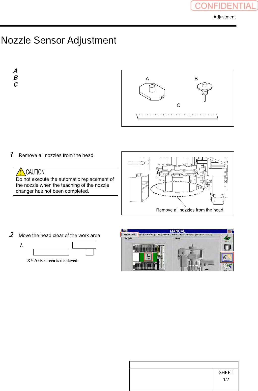
[Necessary jigs]
Jig nozzle for nozzle changer
Nozzle (used in production)
Scale (about 300 mm)
[Adjust the sensor attachment height]
Click in an order of MANUAL menu
AXIS MOTION tab XY button.
HLGB-10415-01
Nozzle Sensor Adjustment
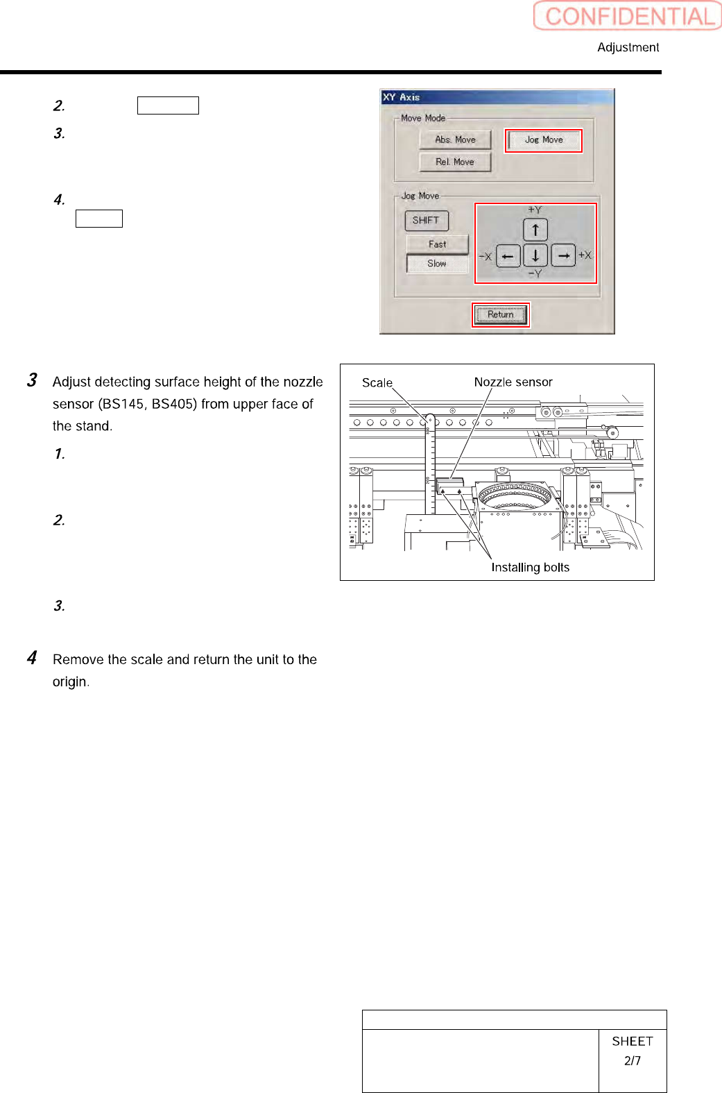
Click the Jog Move button.
Press the cursor key to move the head
to a position where working is easily
performed.
After moving the head, click the
Return button to close the XY Axis
screen.
Use a scale to measure detecting
surface height of the nozzle sensor
from upper face of the stand.
Loosen the installing bolts (2-CP2.5x8)
to adjust installing height of the nozzle
sensor so that the detecting surface
height becomes 203[mm].
After adjusting height, loosen the
installing bolts to fix the nozzle sensor.