MAN00000772_SI-G200BB_SVCPDFA.pdf - 第334页
HLGB-10415-01 Nozzle Sensor A djustment Click the Jog Move button. Press the cursor key to move th e head to a position where w orki ng is ea s ily performed. After moving the head, click the Return button to close the X…
HLGB-10415-01
Nozzle Sensor Adjustment
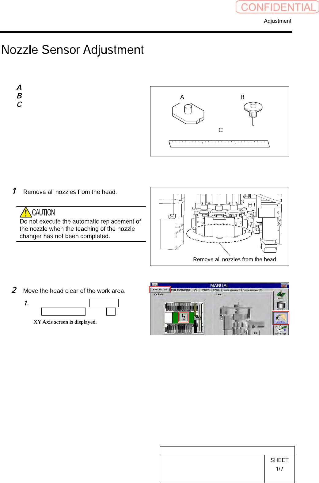
[Necessary jigs]
Jig nozzle for nozzle changer
Nozzle (used in production)
Scale (about 300 mm)
[Adjust the sensor attachment height]
Click in an order of MANUAL menu
AXIS MOTION tab XY button.
HLGB-10415-01
Nozzle Sensor Adjustment
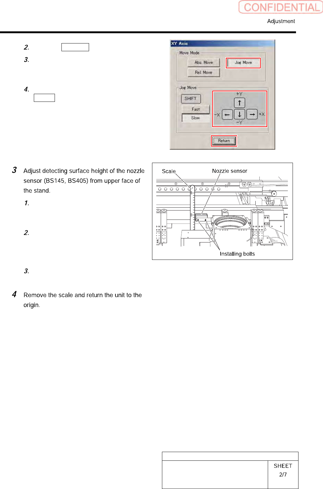
Click the Jog Move button.
Press the cursor key to move the head
to a position where working is easily
performed.
After moving the head, click the
Return button to close the XY Axis
screen.
Use a scale to measure detecting
surface height of the nozzle sensor
from upper face of the stand.
Loosen the installing bolts (2-CP2.5x8)
to adjust installing height of the nozzle
sensor so that the detecting surface
height becomes 203[mm].
After adjusting height, loosen the
installing bolts to fix the nozzle sensor.
HLGB-10415-01
Nozzle Sensor Adjustment
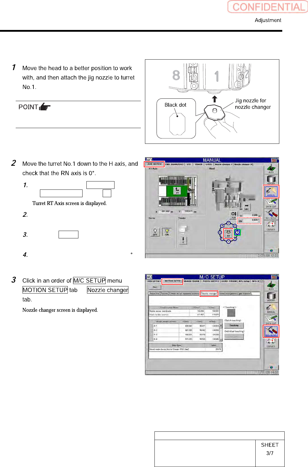
[Coordinate value setup for sensor]
Attach the jig nozzle so that the black dot on the
bottom of the nozzle comes inward of the turret.
Click in an order of MANUAL menu
AXIS MOTION tab RT button.
Operate the RT axis screen and move
the turret No.1 down to the H axis.
Click the Return button to close the
Turret RT Axis screen.
Check that angle of the RN axis is 0
on the axis operation screen.