MAN00000772_SI-G200BB_SVCPDFA.pdf - 第347页
HLGB-10419-01 Fixed Ca mera Pickup Check Sensor Adjustment Carry out working with care not to damage the fiber cable for parts presence/absence detecting sensor . Open the cover for the sensor amplifier . T urn the SET/R…
HLGB-10419-01
Fixed Camera Pickup Check Sensor
Adjustment
Perform this operation for fixed camera pickup check sensors on both of front and rear sides.
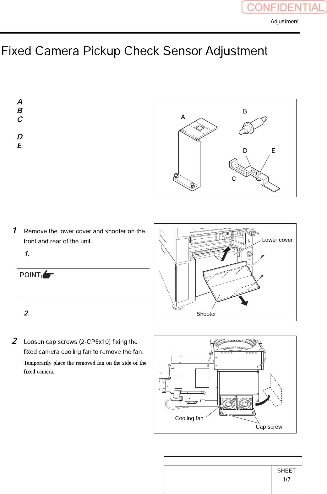
[Necessary jigs]
Fixed camera Jig base (G200)
Nozzle Jig for fixed camera
Fixed camera parts presence/absence
sensor adjustment Jig
Sensor adjusting nozzle (1)/long thin
Sensor adjusting nozzle (2)/short thick
[Procedure]
Loosen screw (2-+T4x8) to remove the
lower cover.
Tile the lower cover slightly toward you and pull
the fan cable to remove the lower panel.
Loosen screw (2-+T4x8) to remove the
shooter.
HLGB-10419-01
Fixed Camera Pickup Check Sensor
Adjustment
Carry out working with care not to damage the
fiber cable for parts presence/absence detecting
sensor.
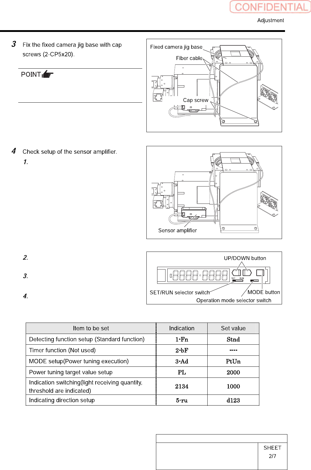
Open the cover for the sensor
amplifier.
Turn the SET/RUN selector switch to
SET.
Press the MODE button to select item
to be set.
Press the UP/DOWN button to change
the set button.
L D
HLGB-10419-01
Fixed Camera Pickup Check Sensor
Adjustment
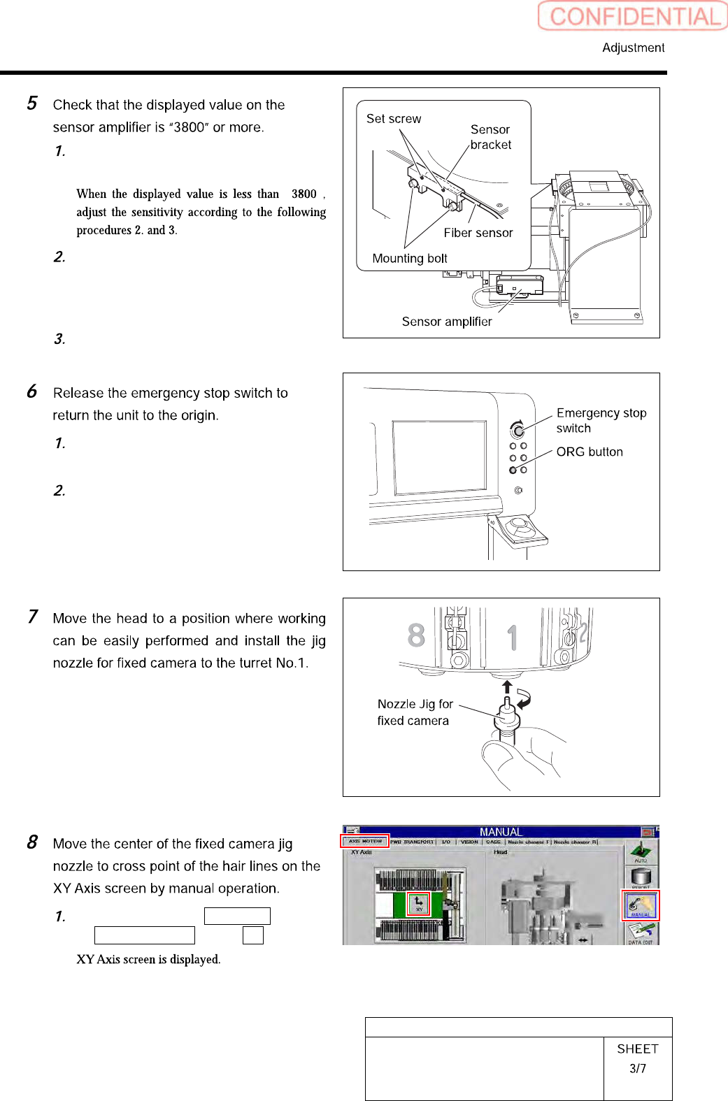
Check that the displayed value on the
sensor amplifier is “3800” or more.
“ ”
Loosen the sensor bracket mounting
bolt, and move the sensor bracket up
and down, to left and right to adjust
the fiber sensor mounting position.
Loosen the set screw to adjust rotating
direction of the pickup check sensor.
Turn the emergency stop switch to
release emergency stop.
Click the [ORG] button to return the
system to the original position.
Click in an order of MANUAL menu
AXIS MOTION tab XY button.