MAN00000772_SI-G200BB_SVCPDFA.pdf - 第349页
HLGB-10419-01 Fixed Ca mera Pickup Check Sensor Adjustment Click the Jog Move button. Press the cursor key and move the center of the fi xe d cam e ra j ig nozzle to cross point of the hair lines on the P ARTS DISPLA Y s…
HLGB-10419-01
Fixed Camera Pickup Check Sensor
Adjustment
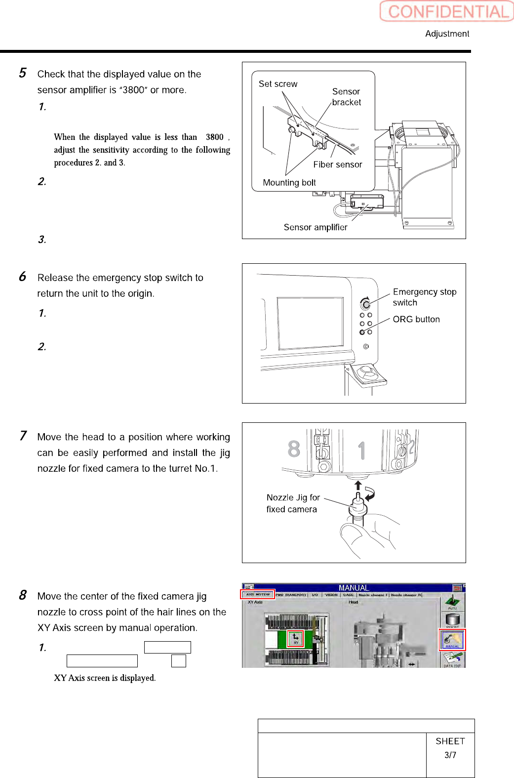
Check that the displayed value on the
sensor amplifier is “3800” or more.
“ ”
Loosen the sensor bracket mounting
bolt, and move the sensor bracket up
and down, to left and right to adjust
the fiber sensor mounting position.
Loosen the set screw to adjust rotating
direction of the pickup check sensor.
Turn the emergency stop switch to
release emergency stop.
Click the [ORG] button to return the
system to the original position.
Click in an order of MANUAL menu
AXIS MOTION tab XY button.
HLGB-10419-01
Fixed Camera Pickup Check Sensor
Adjustment
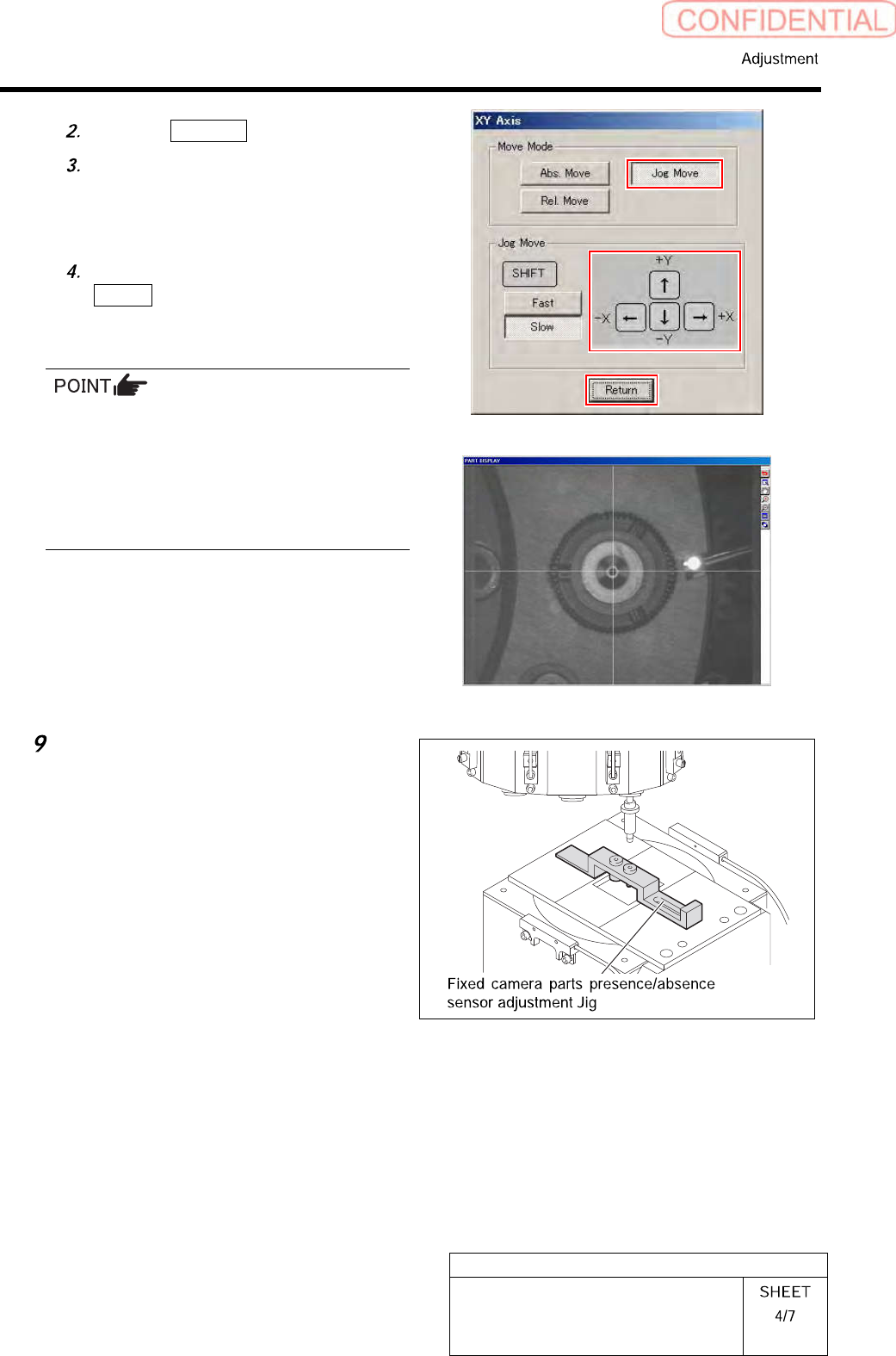
Click the Jog Move button.
Press the cursor key and move the
center of the fixed camera jig nozzle to
cross point of the hair lines on the
PARTS DISPLAY screen.
After moving the head, click the
Return button to close the XY Axis
screen.
When performing this operation immediately
after auto calibration, absolute-move the head to
the position described
on#PbPointForFixedCam1 in Calibration.dat
using MANUAL/AXIS MOTION menu to adjust
fine position. More accurate position adjustment
will be possible.
Put “Fixed camera parts presence/absence
sensor adjustment jig“ on “Fixed camera
jig base“.
HLGB-10419-01
Fixed Camera Pickup Check Sensor
Adjustment
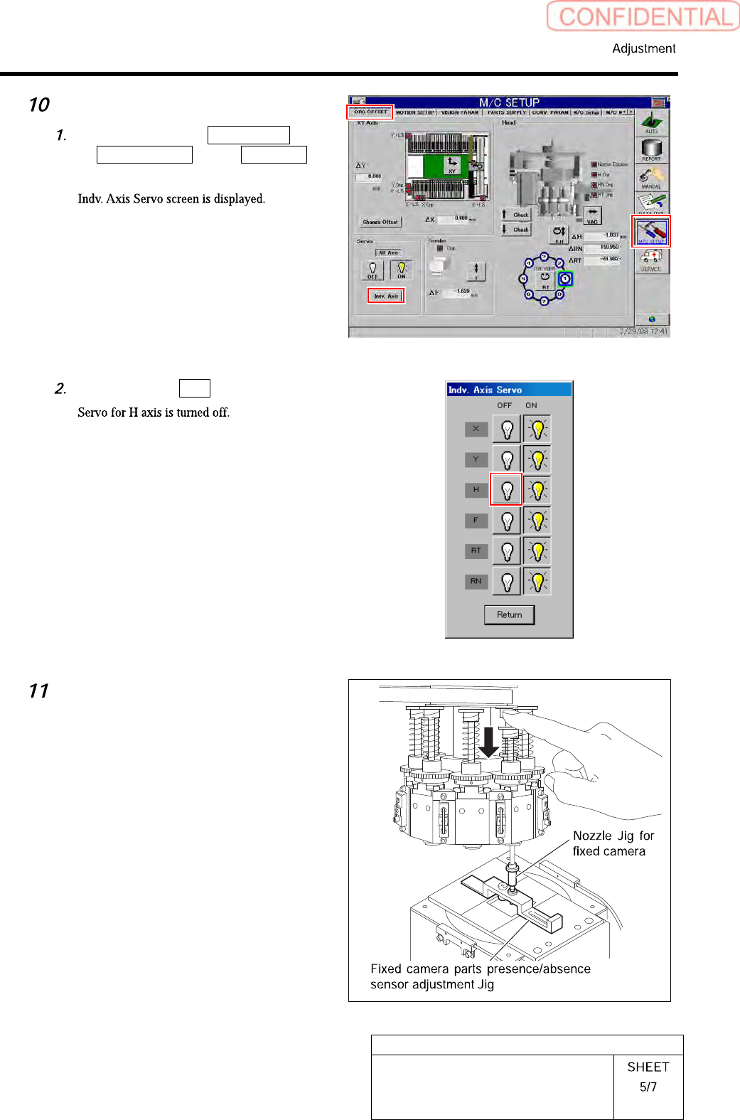
Servo off only H-axis.
Click in an order of M/C SETUP menu
ORG OFFSET tab Indv. Axis
button.
Click the servo OFF button for H axis.
Check whether “Sensor adjusting nozzle
(1) “ is under the “Jig nozzle for fixed
camera“. Fix “Fixed camera parts
presence/absence sensor adjustment
jig“ After check the position of “Sensor
adjusting nozzle (1) “.