MAN00000772_SI-G200BB_SVCPDFA.pdf - 第353页
HLGB-10420-01 Area Sensor Optical Axis A dj ustment Supply s ection of cass ette sp ecif i cation is different from t hat of t ray s pecifi c ation in optical axis position of area s ens o r . Be careful of se nsor mount…
HLGB-10419-01
Fixed Camera Pickup Check Sensor
Adjustment
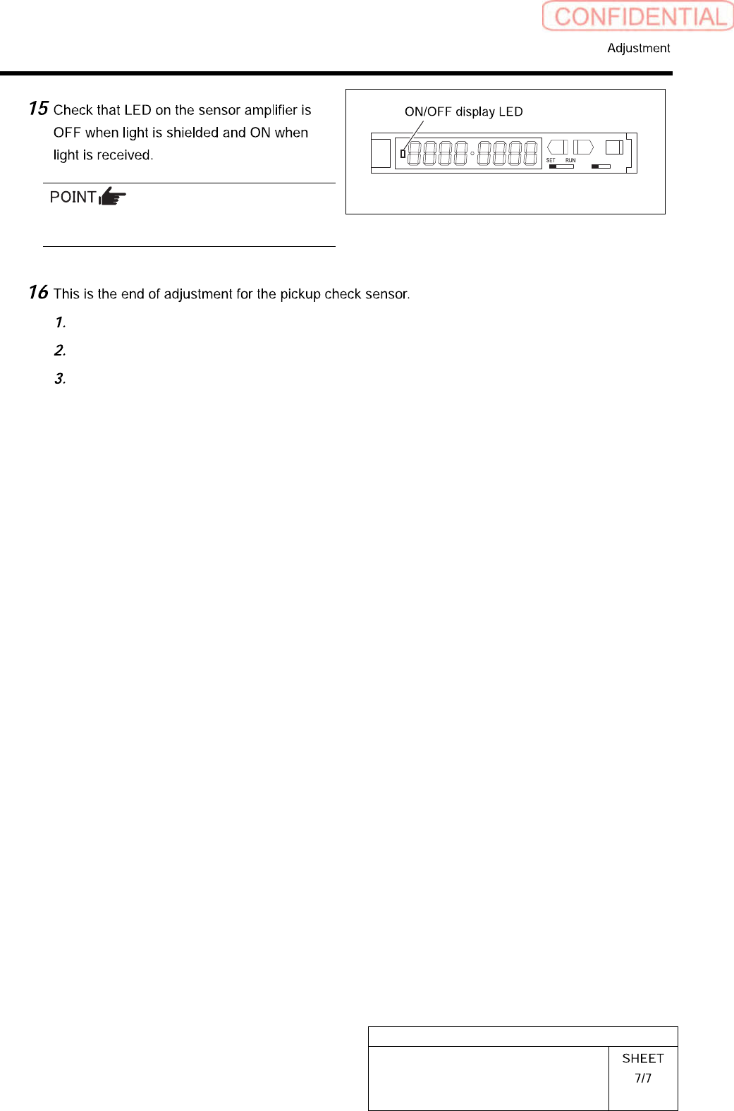
Status of the sensor can be checked even by the
I/O monitor.
L D
Remove all jigs.
Install the cooling fan for fixed camera to the previous position.
Install the shooter and the lower cover.
HLGB-10420-01
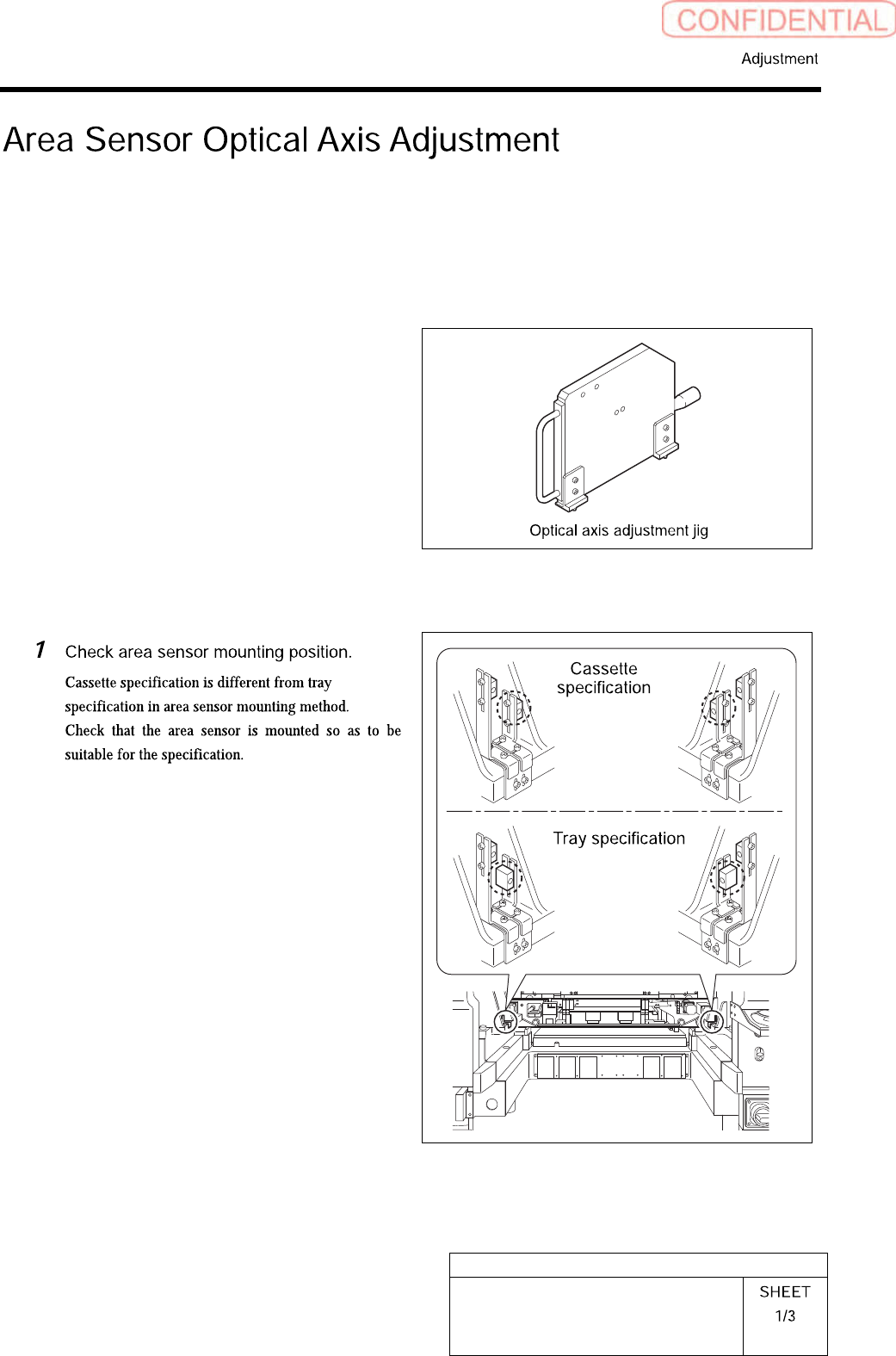
Area Sensor Optical Axis Adjustment
Supply section of cassette specification is different from that of tray specification in optical axis
position of area sensor. Be careful of sensor mounting position and hole position for jig before
carrying out optical axis adjustment.
[Necessary jigs]
• Optical axis adjustment jig
[Procedure]
HLGB-10420-01
Area Sensor Optical Axis Adjustment
Check that the replacing carrier has
been raised.
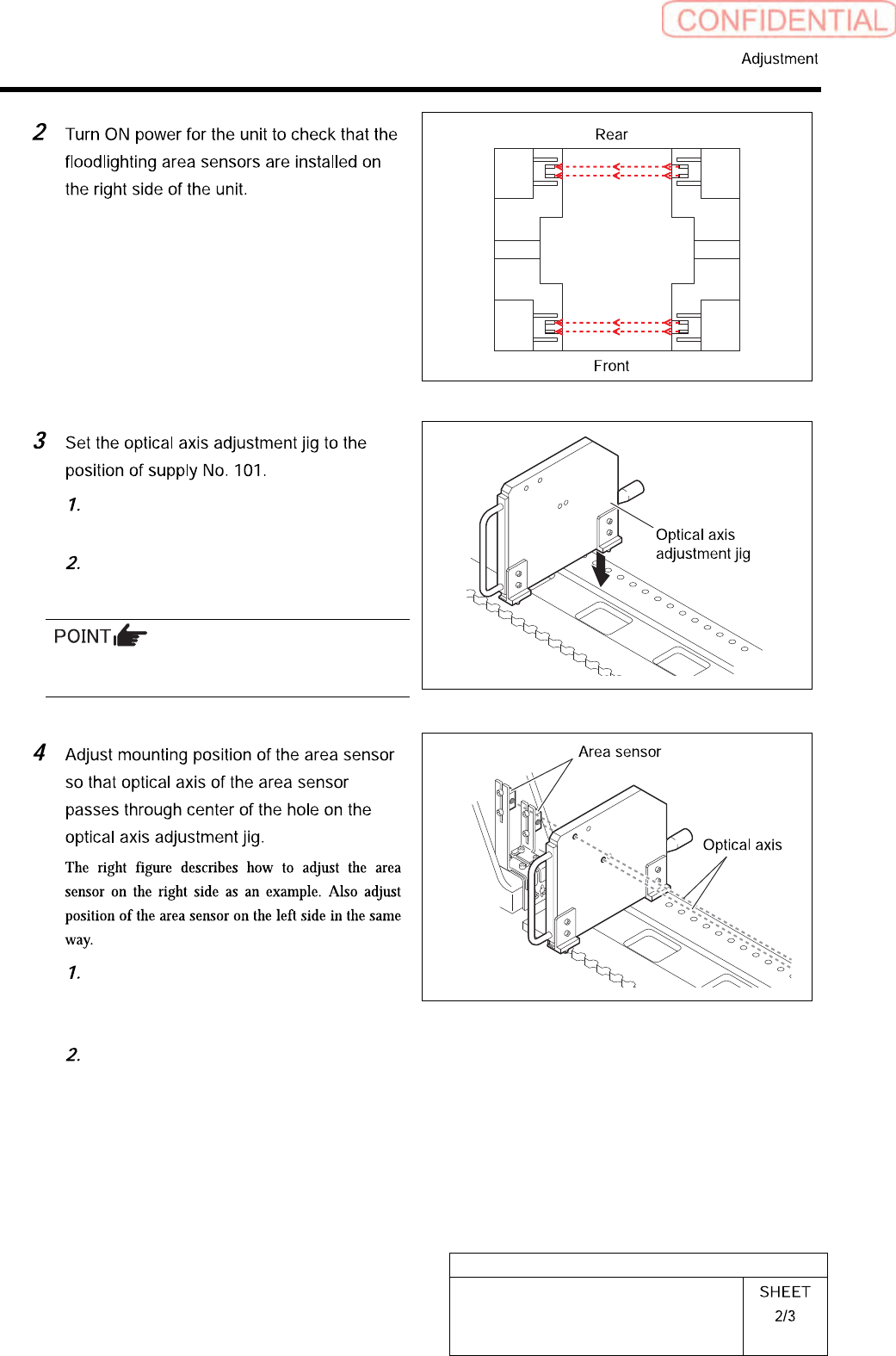
Set the optical axis adjustment jig on
the cassette table of supply No.101.
There should be no gap between the optical axis
adjustment jig and the cassette table.
Loosen the mounting bolts for the area
sensor to adjust up and downward
positions.
Loosen the cap screw on the lower side
of the bracket to adjust forward and
backward position of the area sensor.