MAN00000772_SI-G200BB_SVCPDFA.pdf - 第354页
HLGB-10420-01 Area Sensor Optical Axis A dj ustment Check that th e replacing carrier has been raised. Set the optical ax is adj ustm ent jig on the cassette table of supp l y No.101. There shoul d be no gap between the …
HLGB-10420-01
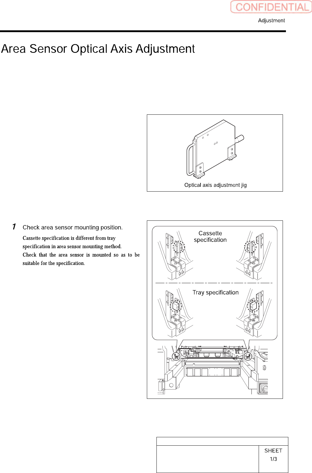
Area Sensor Optical Axis Adjustment
Supply section of cassette specification is different from that of tray specification in optical axis
position of area sensor. Be careful of sensor mounting position and hole position for jig before
carrying out optical axis adjustment.
[Necessary jigs]
• Optical axis adjustment jig
[Procedure]
HLGB-10420-01
Area Sensor Optical Axis Adjustment
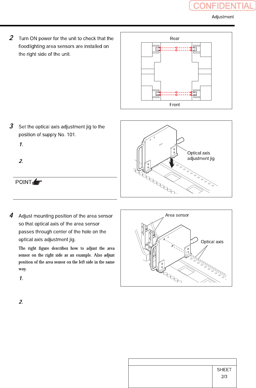
Check that the replacing carrier has
been raised.
Set the optical axis adjustment jig on
the cassette table of supply No.101.
There should be no gap between the optical axis
adjustment jig and the cassette table.
Loosen the mounting bolts for the area
sensor to adjust up and downward
positions.
Loosen the cap screw on the lower side
of the bracket to adjust forward and
backward position of the area sensor.
HLGB-10420-01
Area Sensor Optical Axis Adjustment
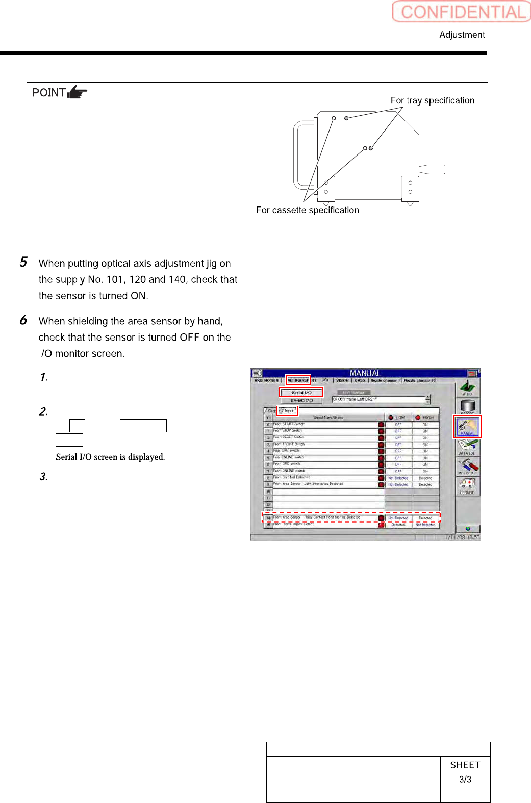
Cassette specification is different from tray
specification in jig hole to be used.
Holes on the front are for cassette specification
and holes on the back are for tray specification
with the optical axis adjustment jig being placed
on the cassette table.
Remove the optical axis adjustment
jig.
Click in an order of MANUAL menu
I/O tab Serial I/O button
Input tab.
When shielding the area sensor by
hand, check that the sensor is turned
OFF.