MAN00000772_SI-G200BB_SVCPDFA.pdf - 第57页
Install Tray Unit (Including machine modification) SHEET 18/73 WKGB-10104-03 Installing Tray Unit (Including machine modificat ion) 6 Connection of tray coupling cable 1. Loosen the CP6x12 and pull pout the I/O u nit…
Install Tray Unit (Including machine modification)
SHEET
17/73
WKGB-10104-03
Installing Tray Unit
(Including machine modification)
3.
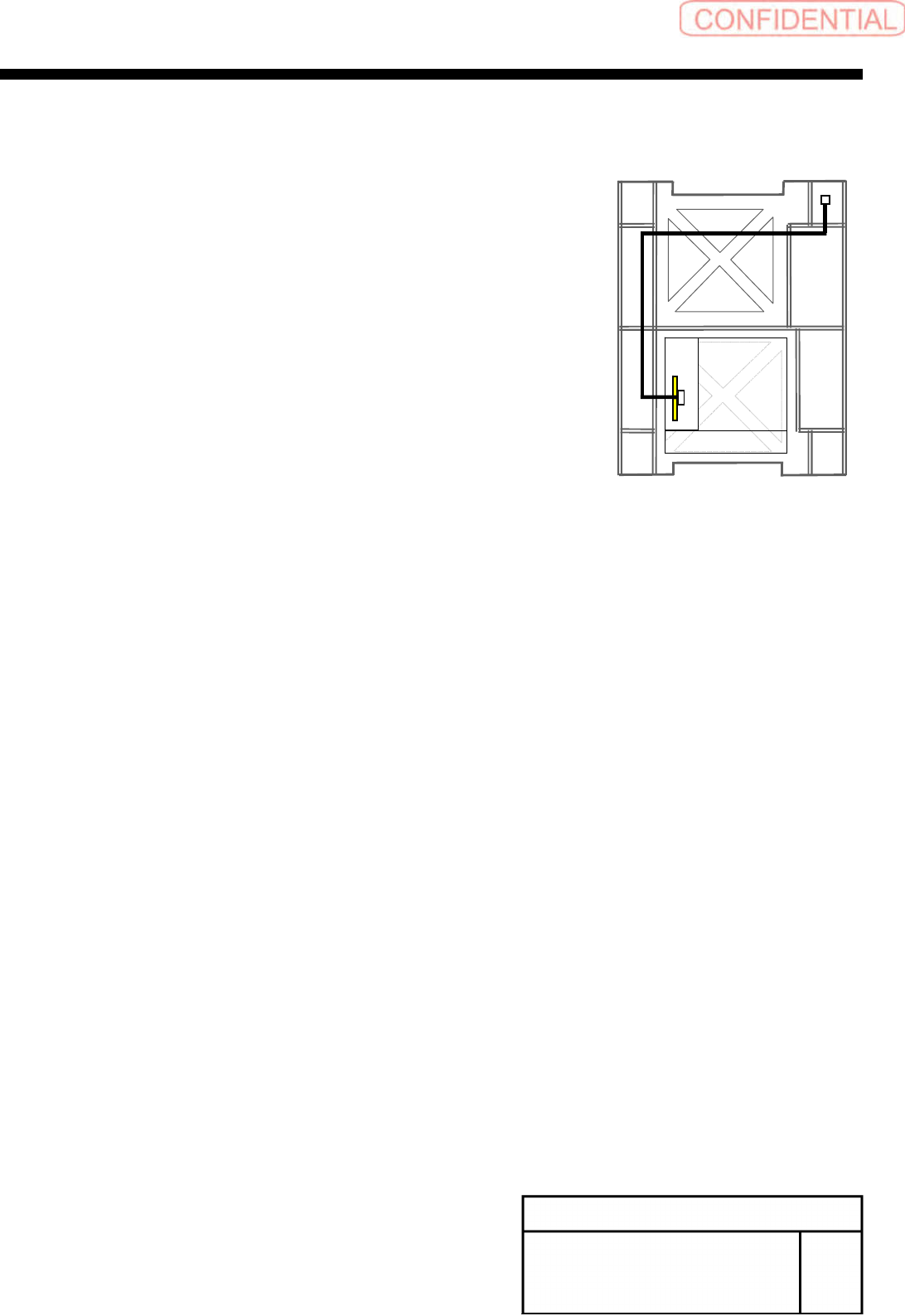
Connect the EI0-14 of EX2 I/O cable to the CN14
of EX2 I/O board and wire EX2 I/O cable to rear
side of mounter.
4.
Connect the TY-CTL3 of the EX2 I/O cable to
TY0-CTR3 of the tray I/F panel.
Front
Install Tray Unit (Including machine modification)
SHEET
18/73
WKGB-10104-03
Installing Tray Unit
(Including machine modification)
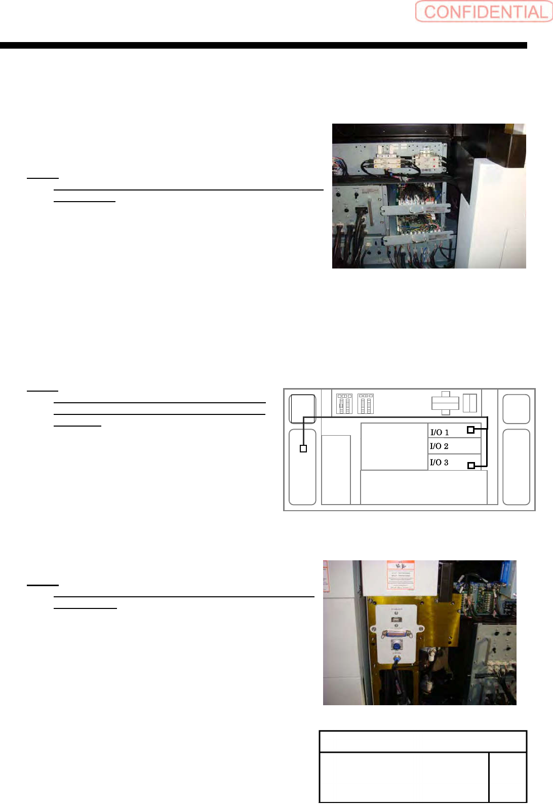
6
Connection of tray coupling cable
1.
Loosen the CP6x12 and pull pout the I/O unit 1
and I/O unit 3 to a position where working can be easily
performed.
NOTE:
Do not forcedly pull them out. Otherwise, the cable may
be damaged.
2.
Connect the ELR-12 to CN12 on the emergency
I/L Board in the I/O unit 3, and connect SR-5,
SR-16 to CN5, CN16 on the safety relay board in
the I/O unit.
NOTE:
Remove the jumper connector connected
CN12 on E I/L board and connected CN5 on
SR board.
7
Install the tray I/F panel with the
2-CP6X8.
NOTE:
Connect terminal connectors to the TY-MLOUT and
TY-CTLOUT.
TY-CTL1
TY-CTL2
Install Tray Unit (Including machine modification)
SHEET
19/73
WKGB-10104-03
Installing Tray Unit
(Including machine modification)
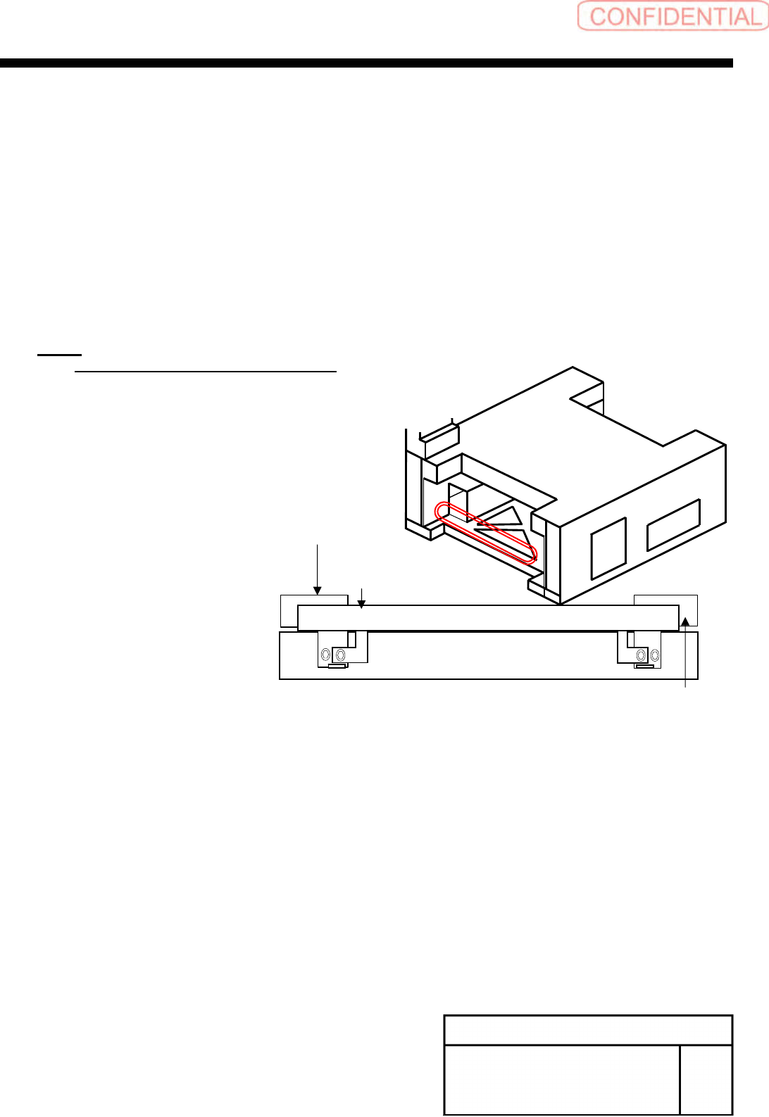
[Removal of under cover]
1
Remove the rear center cover and
shooter.
2
Loosen the 4-CP4x8 to remove the
under cover bracket on the rear side.
3
Loosen the CP4x8 to remove the cover
stay (R) on the rear side.
NOTE:
Use the cover installing stay (L) as it is.
Under cover bracket on rear side
Cover installing stay on the rear
side (R)
Cover installing stay (L) on rear side