MAN00000772_SI-G200BB_SVCPDFA.pdf - 第699页
XY axis movable parts RPGB-1 1201-01 Change Proce d ure for X Axis LM-GUIDE SEET 4 / 7 3, Set LM-guide hold jig POINT Presses side is seen a t back. Position order sta rt is from left-hand side І , П , ( Ш · · · ) 4, Tig…
XY axis movable parts
RPGB-11201-01
Change Procedure for
X Axis LM-GUIDE
SEET
3
/
7
[Reassembly of LM-guide]
1, Prior work
1-1 Apply grease into new LM-guide
POINT
Application grease (AFC-grease Maker: THK) use a suitable amount
Be careful to not apply much quantity
Be careful of slide block come off and ball fall
1-2 Cleaning of the LM-guide installation surface
POINT
Polish an installation surface with an oil stone
Wipe dust at clean cloth
2, Install LM-guide and temporarily stop the screw
POINT
From X-axis motor side view
Left sides LM-guide have not KB mark
Right sides LM-guide have KB mark
(KB mark is written in the end of serial No)
Be careful base line arranges install to the outside
(Base line in the installation side)
baseline
baseline
SERIALNo,(theendofaKBmark)
SerialNo,○○○・・・KB
SerialNo,○○○・・・
XY axis movable parts
RPGB-11201-01
Change Procedure for
X Axis LM-GUIDE
SEET
4
/
7
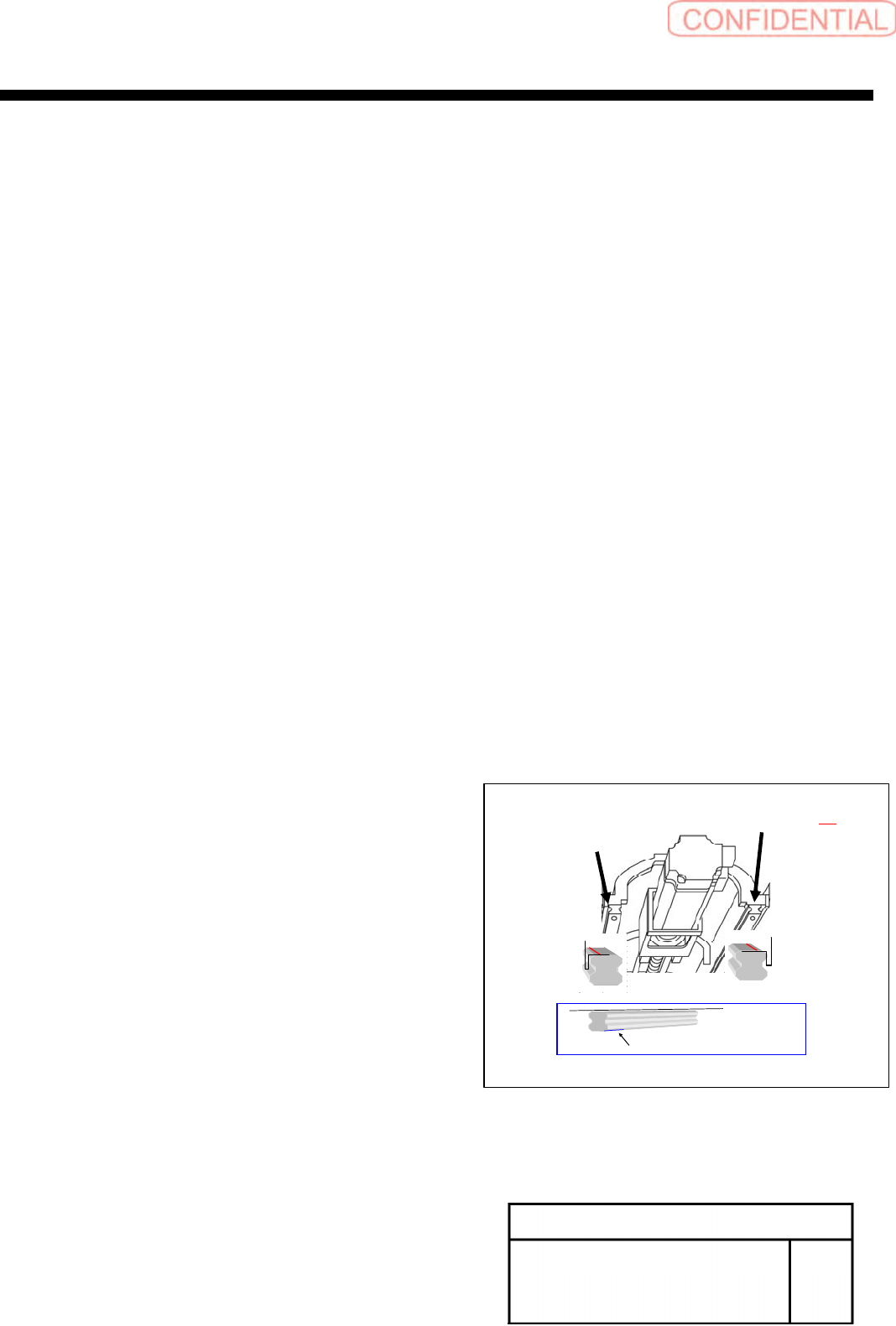
3, Set LM-guide hold jig
POINT
Presses side is seen at back.
Position order start is from left-hand side
І , П , (Ш···)
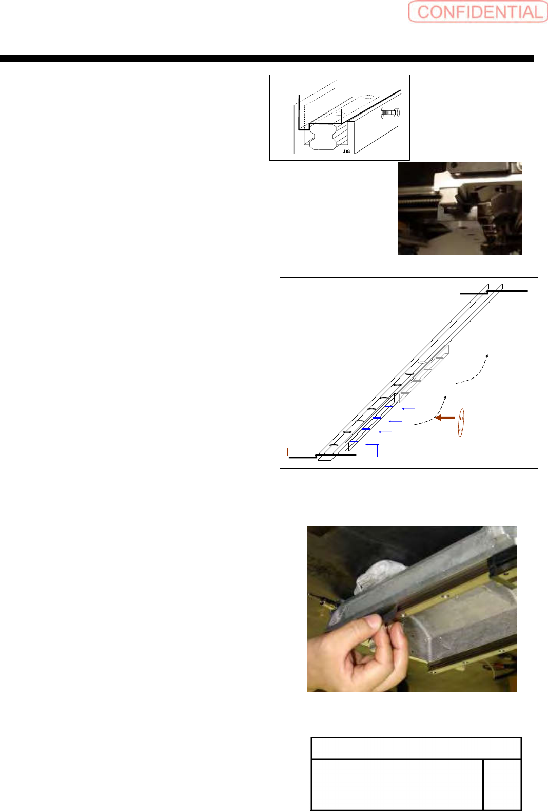
4, Tighten of tension screw (M4) for
press to L M-guide and base
After tighten of LM-guide fixed screw
M4 tension screw Tightening torque 50 (cN.m)
LM-guide screw Tightening torque 206(cN.m)
POINT
Presses side is seen at back.
Position order start is from left-hand side
1,2,3,(4···)
5, JIG moves to the next position
Please repeat 3.4 works
6, Confirm the gap between base level and LM-guide
POINT
Thickness gauge0.02mm do not enter
Leftside
1
2
3
4
・
・
・
M4Tensionscrew
Ⅰ
Ⅱ
Ⅲ
XY axis movable parts
RPGB-11201-01
Change Procedure for
X Axis LM-GUIDE
SEET
5
/
7
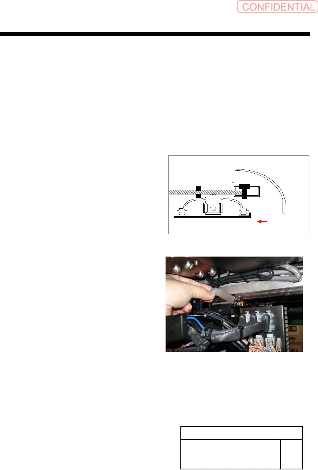
7, Cleaning of the slide block and installation surface
8, Match a slide block with the installation side of
the X-axis Base Saddle, Temporarily stop the screw
(LM-guide of Basis side and Subordinate side)
9, Press to slide block and installation surface of
the X-axis Base Saddle Then tighten it
(Basis side LM-guide)
Confirm the gap between base level and LM-guide
POINT
Thickness gauge0.02mm do not enter
M/C
OUTSIDE
M/C
INSIDE