ysm20r_cabpara.pdf - 第21页
27 1 1. Specications YSM20R (SESMK18400-00) v2.001 Environmental conditions T emperature Fu nction assuranc e : 15 to 35°C Accuracy assu r ance : 20 to 28° C Humidity Allowable r ange : 20 to 80% (No c ondensation) Opti…
26
11. Specications
YSM20R (SESMK18400-00) v2.001
Air supply
source
0.45 MPa or more (4.5 kgf / cm
2
or more), clean and dry air
* To maintain a sufficient air flow rate, prepare a supply air hose with an inside diameter of 8mm or more.
* Supply the air with excellent quality that has passed through the air dryer and air filter on the line side
of the air supply source. (The air filter built-into this machine is intended to protect the machine.
To maintain the function and performance of this machine at their optimal levels for an extended period
of time, the air must be kept clean and dry on the line side of the customer’s air supply source.)
* Set pressure to 0.40 MPa (0.39MPa
to
0.41MPa).
Air
consumption
flow rate
Average consumption Max consumption
YSM20R-2 2Head
High-speed multi-
purpose (HM) head x 2
240 ℓ / min [ANR] 340 ℓ / min [ANR]
YSM20R-2 2Head
Odd-shaped
components (FM) head x 2
140 ℓ / min [ANR] 320 ℓ / min [ANR]
YSM20R-1 1Head
High-speed multi-
purpose (HM) head x 1
130 ℓ / min [ANR] 290 ℓ / min [ANR]
YSM20R-1 1Head
Odd-shaped
components (FM) head x 1
80 ℓ / min [ANR] 280 ℓ / min [ANR]
* When the machine is equipped with the ATS carriage, it is necessary to add approx. 10 liters / min.
(ANR) to the air consumption flow rate shown above.
* "ANR" is an abbreviation of "Atmosphere Normal de Reference" and shows the standard reference
atmospheric status (temperature is 20°C, relative humidity is 65%, and absolute pressure is 101.3 kPa
(1.03 kgf / cm
2
or 760mmHg)).
Power
supply
Power requirement : 3-phase AC power, 200 / 208 / 220 / 240 / 380 / 400 / 416 V ± 10%
Frequency : 50Hz / 60Hz
Power capacity : 10.4kVA
Average power consumption : 1.9kW (under standard operating conditions)
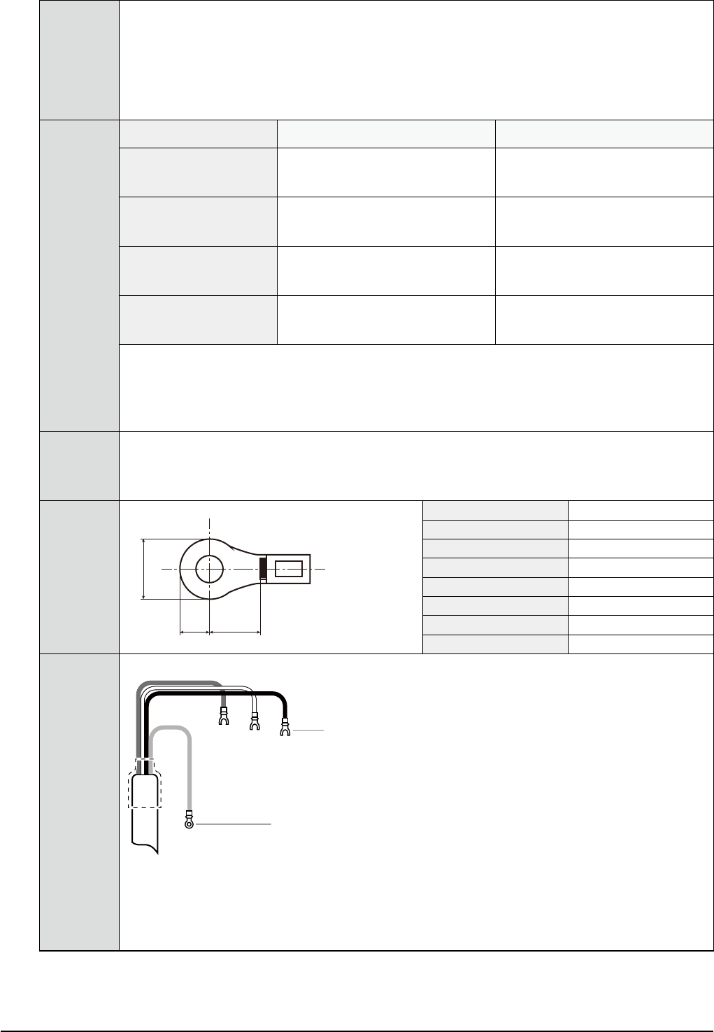
Power cable
terminal
size
b c
a
Terminal Part No. KLW-M643A-00X
Manufacturers TOYOGIKEN CO.,LTD
Manufacturers Part No. FPS-80
Bolt diameter M5
Max. Terminal width (a) 12.2 mm
Max. Terminal length(b) 6.5 mm
Min. Terminal length(c) 7 mm
Tightening torque 2.0-3.0N
・
m
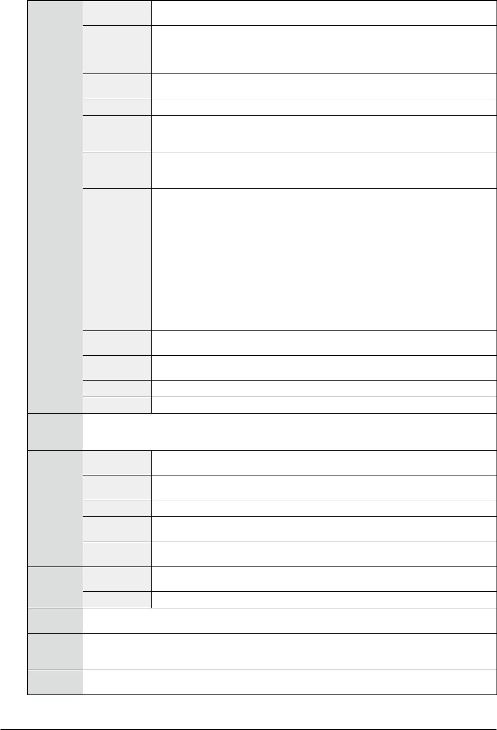
Power
supply
connection
Power cable conductor cross-section area : 6mm
2
or more.
L1
L2
L3
PE
Ring-tongue crimp terminal
Insulated crimp terminal
* To prevent electric shock accidents, make sure that the power source is shut down securely
before connecting the power cable.
* Connect the main body grounding cable securely.
* L1, L2, and L3 show the 3-phase AC power cables and PE shows the grounding cable.
27
11. Specications
YSM20R (SESMK18400-00) v2.001
Environmental
conditions
Temperature Function assurance : 15 to 35°C
Accuracy assurance : 20 to 28°C
Humidity Allowable range : 20 to 80% (No condensation)
Optimal range : 50 to 60%
* Keep a humidity of approx. 40% or more as static electricity prevention measures.
* When using an industrial humidifier, use water equivalent to DI water.
Transient voltage
category
category III
Pollution degree
degree 2
Atmosphere There shall be no dirt and dust.
There shall be no organic solvent vapor, sulfurous acid gas, chlorine gas, and flammable
gas.
Altitude 1,000 m or less above sea level
* This avoids that the air pressure or cosmic ray adversely affects the insulation
performance.
Installation floor
conditions
The floor withstanding load capacity shall be approx. 850kg / m
2
.
* For the floor withstanding load capacity, consult the specialists who know the installation
place well with the information on equipment weight, floor sharing area, and adjuster foot
positions.
* The floor shall be flat and have sufficient strength so that it does not vibrate during
operation. The floor shall have the concrete strength or its equivalent.
In particular, wooden floor, office floor, and grating are not allowed to use.
* If the floor is not concrete, consult the specialists who know the installation place well and
construct the reinforcement work for the portions where the equipment adjuster feet are
placed.
* When the feeder exchange carriage is shared by different machine models, a flatness of
10mm or less is required for the floor installation areas of all target equipment.
Ambient noise There shall be no significant noise.
Equipment warning beep should be heard without fail.
Ambient light Strong light such as sunlight does not enter the vision system
(optical image processing system).
Noise immunity See "10.7 CE marking".
Noise emission See "10.7 CE marking".
Board
transport
height
900mm ± 10mm (From the floor surface to the upper surface of the conveyor belt)
Input data Number of
mounting points
12,800 points (Note that the number of mounting points decreases depending on the
number of boards, the number of blocks, or the number of fiducial marks.)
Component
types
255 types / board
Board data 100 MB / unit
Number of
fiducial marks
128 sets / board
Data entry
method
Data entry unit supplied with the machine main unit
Positioning
resolution
X-axis / Y-axis /
Z-axis
0.001mm
R-axis 0.001°
External
interface
LAN*, 1 port (See "7.5 Network" and "7.6 Anti-virus measures".)
Internal
memory
Built-in 4GB flash card *, 1 pc.
* For storage of files, such as OS, mounter application software, board data, component data,
vision data, machine information, and production history information, etc.
External
memory
USB flash memory with a capacity of 8GB or more *, 1 pc.
(Supplied as standard accessory : For data backup)
28
11. Specications
YSM20R (SESMK18400-00) v2.001
11.2 Mounting capability
YSM20R-2 (2Head) High-speed multi- purpose (HM) head x 2
Type PV : 95,000CPH (0.038 sec / CHIP) * YAMAHA optimal conditions
* Compatibility with sATS30NS, Nonstop feeder exchange system. 0201 or more component
correspondence. Scan camera □ 12 mm specification.
Type SV : 90,000CPH (0.040 sec / CHIP) * YAMAHA optimal conditions
* Not compatibility with sATS30NS, Nonstop feeder exchange system. 03015 or more component
correspondence. Scan camera □ 8 mm specification.
The mounting capability when using the customer's boards and components can be estimated (calculated) by
using the following tools. Consult with YAMAHA for details.
-1- Simple tact simulation program
-2- YAMAHA SMT line support software Y.FacT / P-Tool
11.3 Mounting accuracy
When using YAMAHA standard components for evaluation, test board, and two-faced adhesive tape.
CHIP components ± 0.035mm (± 0.025mm) Cpk
≧
1.0 (3σ)
QFP components ± 0.035mm (± 0.025mm) Cpk
≧
1.0 (3σ)
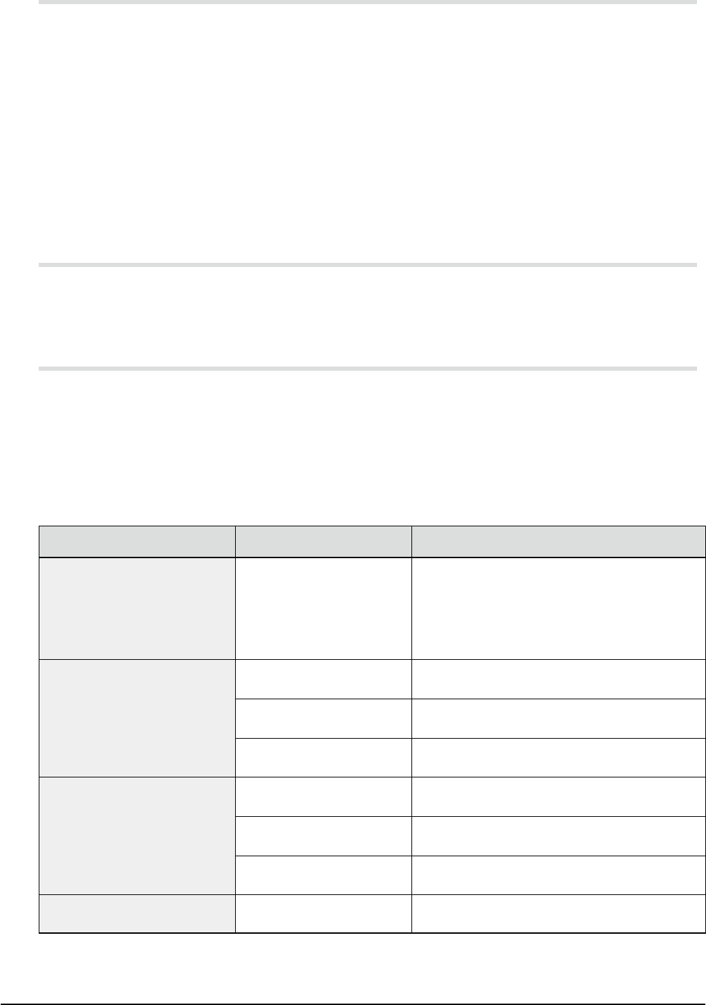
11.4 Applicable components
Components for which normal mounting can be expected when all conditions are good
The mounting capability of this machine is significantly affected not only by the machine performance, but
also by various conditions such as the components and boards. Determining whether or not a given
component can be mounted requires a test operation with an actual sample of the component in question.
Some guidelines for Applicable components are given in the table below.
(Factors which determine whether or not a component can be used include the following: electrode lead's
bend, lift and optical surface condition, ball electrode's deformation and height variations, background color,
glossiness condition, component's weight, pickup nozzle's contact surface condition, and board warp, etc.)
Component type Typical component size Remarks
Square chip components
Cylindrical chip components
Mini-mold transistors
Power transistors
Aluminum electrolytic capacitors,
etc.
0.2 x 0.1mm to 12 x 12mm
* For Type SV, 0.3 x 0.15 mm or more component
correspondence.
Lead electrode components
(SOP, SOJ, QFP, etc.)
5 x 4.5mm to 20 x 20mm
Minimum lead pitch : 0.4mm or less
(0.22mm gap for a reference lead width of 0.18mm)
20 x 20mm to 32 x 32mm
Minimum lead pitch : 0.5mm or less
(0.28mm gap for a reference lead width of 0.22mm)
32 x 32mm to 55 x 55mm
Minimum lead pitch : 0.65mm or less
(0.35mm gap for a reference lead width of 0.30mm)
Ball electrode components (BGA,
etc.)
* Consult us for CSP with micro-ball
electrodes.
Up to 20 x 20mm
Reference : Minimum ball diameter is 0.18mm or larger
Reference : Minimum ball pitch is 0.3mm or larger
20 x 20mm to 32 x 32mm
Reference : Minimum ball diameter is 0.22mm or larger
Reference : Minimum ball pitch is 0.37mm or larger
32 x 32mm to 55 x 55mm
Reference : Minimum ball diameter is 0.30mm or larger
Reference : Minimum ball pitch is 0.5mm or larger
Odd-form components such as
connectors, etc.
Up to 55 x 100mm Consult us for each component.
* When handling components with a size exceeding 12 x 12mm and a thickness exceeding 6.5mm, the HM
head requires a multi-view camera (option).
* The FM head can be used with a multi-view camera (standard).