ysm20r_cabpara.pdf - 第24页
30 1 1. Specications YSM20R (SESMK18400-00) v2.001 FM Head Max. buffing stroke of 1.5mm Range II Diameter of 19mm Range I Diameter of 8mm Range I : Height of 6.5mm Range II : Height of 10mm Diameter of 5mm 3mm 28mm or l…
29
11. Specications
YSM20R (SESMK18400-00) v2.001
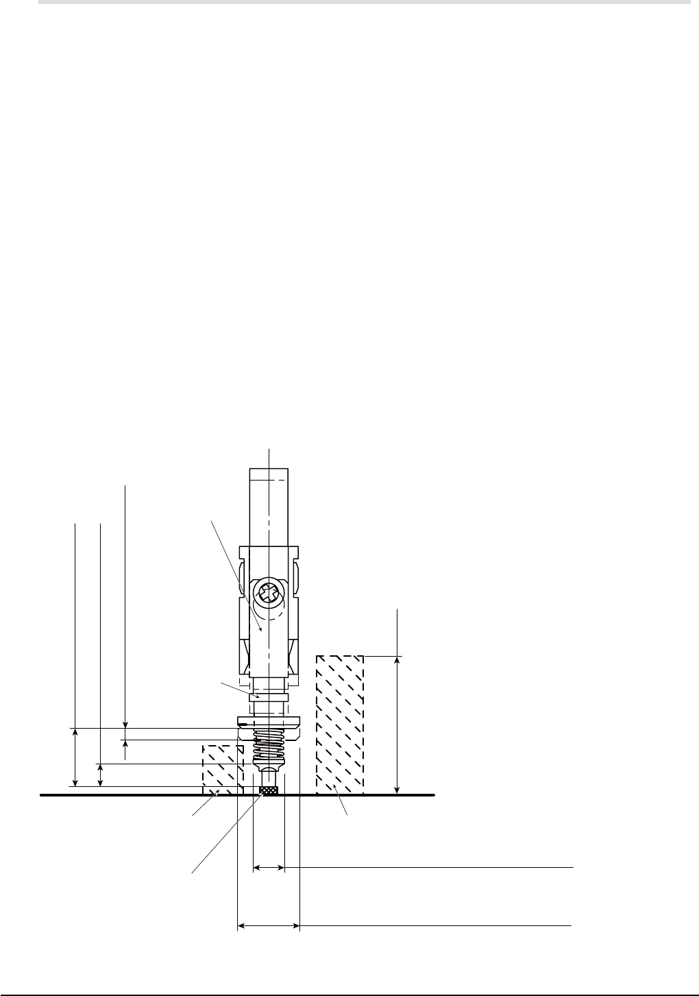
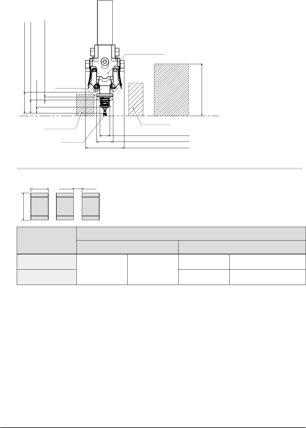
11.5 Component height & mounting restrictions
11.5.1 Height of mountable components
The following describes the height of the components that can be mounted (on the upper side of the board).
High-seed multi (HM) head : 15mm or less
Flexible multi (FM) head : 28mm or less
11.5.2 Mounting restrictions
The correct mounting may not be established according to the relationship between the component size /
height and the nozzle shape.
* In the figure below, since the virtual component (L) is located on the outside of the range I, the correct
mounting is established. If this component is located on the inside of the range, interference may occur.
* In the figure below, since the virtual component (T) is located on the outside of the range II, the correct
mounting is established. If this component is located on the inside of the range, interference may occur.
* An area where any component cannot be mounted may arise around the components that have already
been mounted before carrying into this machine in the same manner as described in the figure below.
* The component presence is not permitted in an area of 3mm from both ends in the transport direction.
support system, programming tool "P-Tool", is prepared to take measures against restrictions on
mounting, such as possibility of interference as described above. Please order this tool. See "3.
Arrangements / -4- Support systems".
HM Head
Range II (Zone where interference may occur)
Range II Diameter of 8mm
Range II : Height of 7.5mm
Range I : Height of 3mm
Max. buffing stroke of 1.5mm
Range I (Zone where interference may occur)
Range I Diameter of 4mm
Head shaft
Nozzle
type 301A
type 302A
type 303A
type 310A
type 311A
type 312A
type 313A
Board face
15mm or less
Virtual component (T)
Mounting
component
Virtual
component (L)
(Max. permissible component height)
type 314A
30
11. Specications
YSM20R (SESMK18400-00) v2.001
FM Head
Max. buffing stroke of 1.5mm
Range II Diameter of 19mm
Range I Diameter of 8mm
Range I : Height of 6.5mm
Range II : Height of 10mm
Diameter of 5mm
3mm
28mm or less
Virtual
component(L)
Virtual component(T)
Mounting
component
(
Max. permissible component heigh
)
Board face
Head shaft
Nozzle
type 311A
type 312A
type 313A
type 314A
type 301A
type 302A
type 303A
type 310A
11.6 Component mounting restrictions
W (width) direction
L (length) direction
Spacing between
adjacent components
Mountable components
("mm" size)
Spacing between adjacent components
Standard 30X nozzles Standard 31X nozzles
0603 square chips
(L0.6 x W0.3mm)
301A nozzle 0.35mm or more
311A nozzles W-direction 0.15mm or more
1005 square chips
(L1.0 x W0.5mm)
312A nozzles W-direction 0.15mm or more
* The above values apply under YAMAHA standard conditions
(when using YAMAHA standard evaluation test board, standard components, and two-faced adhesive
tape).
* The above values may not be obtained depending on the shapes and dimensions of tape reels and
components.
* A mounting space smaller than those shown above requires a custom nozzle (consult us).
31
11. Specications
YSM20R (SESMK18400-00) v2.001
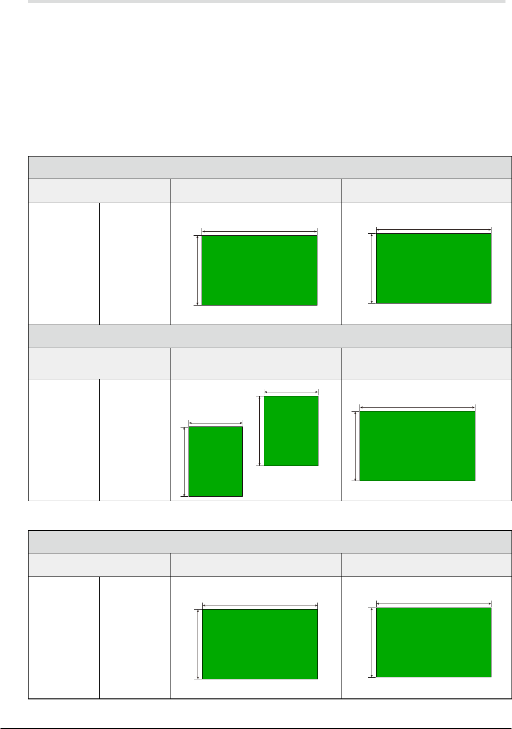
11.7 Applicable board dimensions
YSM20R-2
L size : L50
x
W50 (min.) to L810
x
W 490 (max.) [dual-stage and single lane model]
YSM20R-1
L size : L50
x
W50 (min.) to L810
x
W 490 (max.) [single lane model]
M size : L50
x
W50 (min.) to L360
x
W 490 (max.) [single lane model]
* "L" is a direction along the transport direction while "W" is a direction perpendicular to the transport.
* Maximum dimensions are illustrated below.
YSM20R-2
Single lane model ====> [SL]
Machine layout type
(See "13. References and details".)
Applicable Maximum PCB (L size) Applicable Maximum PCB (M size)
#001
#002
#003
#004
#005
#006
#007
#008
#00S
#00T
#011
#012
#013
#014
#015
#016
#017
#018
#01S
#01T
L810 (Option) / L510 (Standard)
W490
L360 (Standard)
W490
Dual-stage model ====> [DS]
Machine layout type
(See "13. References and details".)
Applicable Maximum PCB
(For dual-stage transport)
Applicable Maximum PCB
(For sigle-stage transport)
#009
#00A
#00B
#00C
#00D
#00E
#00F
#00G
#00U
#00V
#019
#01A
#01B
#01C
#01D
#01E
#01F
#01G
#01U
#01V
L380
W490
L380
W490
L810
W490
YSM20R-1
Single lane model ====> [SL]
Machine layout type
(See "13. References and details".)
Applicable Maximum PCB (L size) Applicable Maximum PCB (M size)
#001
#002
#003
#004
#005
#006
#007
#008
#10S
#10T
#011
#012
#013
#014
#015
#016
#017
#018
#11S
#11T
L810 (Option) / L510 (Standard)
W490
L360 (Standard)
W490