ysm20r_cabpara.pdf - 第25页
31 1 1. Specications YSM20R (SESMK18400-00) v2.001 1 1 .7 Applicable board dimensions YSM20R-2 L size : L50 x W50 (min.) t o L810 x W 490 (max.) [dual-stage and single lane model] YSM20R-1 L size : L50 x W50 (min.) t o …
30
11. Specications
YSM20R (SESMK18400-00) v2.001
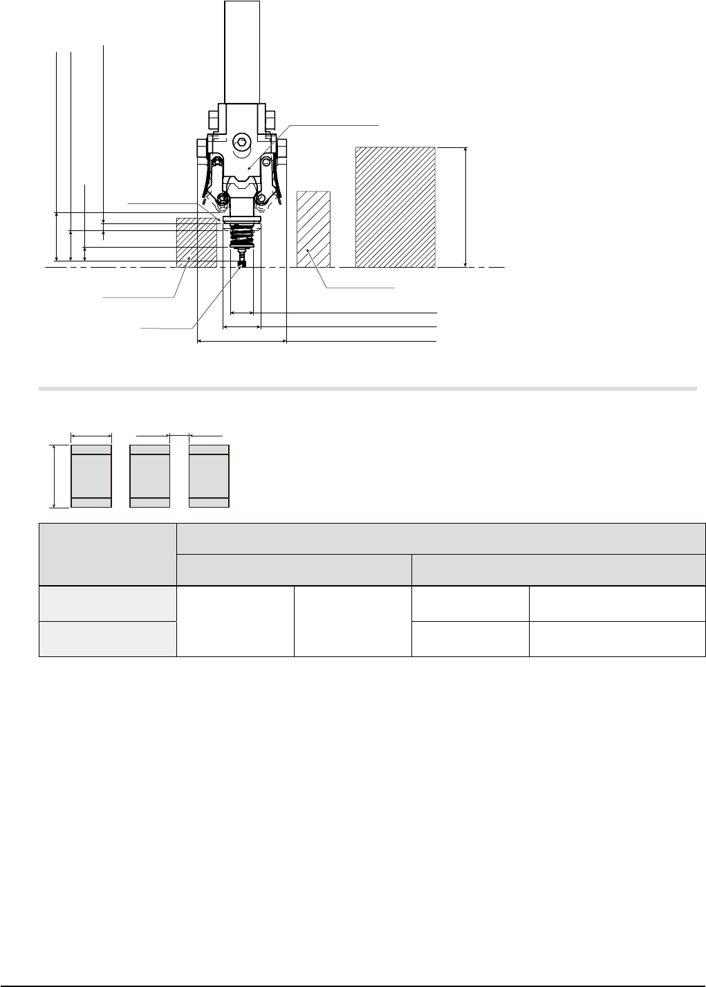
FM Head
Max. buffing stroke of 1.5mm
Range II Diameter of 19mm
Range I Diameter of 8mm
Range I : Height of 6.5mm
Range II : Height of 10mm
Diameter of 5mm
3mm
28mm or less
Virtual
component(L)
Virtual component(T)
Mounting
component
(
Max. permissible component heigh
)
Board face
Head shaft
Nozzle
type 311A
type 312A
type 313A
type 314A
type 301A
type 302A
type 303A
type 310A
11.6 Component mounting restrictions
W (width) direction
L (length) direction
Spacing between
adjacent components
Mountable components
("mm" size)
Spacing between adjacent components
Standard 30X nozzles Standard 31X nozzles
0603 square chips
(L0.6 x W0.3mm)
301A nozzle 0.35mm or more
311A nozzles W-direction 0.15mm or more
1005 square chips
(L1.0 x W0.5mm)
312A nozzles W-direction 0.15mm or more
* The above values apply under YAMAHA standard conditions
(when using YAMAHA standard evaluation test board, standard components, and two-faced adhesive
tape).
* The above values may not be obtained depending on the shapes and dimensions of tape reels and
components.
* A mounting space smaller than those shown above requires a custom nozzle (consult us).
31
11. Specications
YSM20R (SESMK18400-00) v2.001
11.7 Applicable board dimensions
YSM20R-2
L size : L50
x
W50 (min.) to L810
x
W 490 (max.) [dual-stage and single lane model]
YSM20R-1
L size : L50
x
W50 (min.) to L810
x
W 490 (max.) [single lane model]
M size : L50
x
W50 (min.) to L360
x
W 490 (max.) [single lane model]
* "L" is a direction along the transport direction while "W" is a direction perpendicular to the transport.
* Maximum dimensions are illustrated below.
YSM20R-2
Single lane model ====> [SL]
Machine layout type
(See "13. References and details".)
Applicable Maximum PCB (L size) Applicable Maximum PCB (M size)
#001
#002
#003
#004
#005
#006
#007
#008
#00S
#00T
#011
#012
#013
#014
#015
#016
#017
#018
#01S
#01T
L810 (Option) / L510 (Standard)
W490
L360 (Standard)
W490
Dual-stage model ====> [DS]
Machine layout type
(See "13. References and details".)
Applicable Maximum PCB
(For dual-stage transport)
Applicable Maximum PCB
(For sigle-stage transport)
#009
#00A
#00B
#00C
#00D
#00E
#00F
#00G
#00U
#00V
#019
#01A
#01B
#01C
#01D
#01E
#01F
#01G
#01U
#01V
L380
W490
L380
W490
L810
W490
YSM20R-1
Single lane model ====> [SL]
Machine layout type
(See "13. References and details".)
Applicable Maximum PCB (L size) Applicable Maximum PCB (M size)
#001
#002
#003
#004
#005
#006
#007
#008
#10S
#10T
#011
#012
#013
#014
#015
#016
#017
#018
#11S
#11T
L810 (Option) / L510 (Standard)
W490
L360 (Standard)
W490
32
11. Specications
YSM20R (SESMK18400-00) v2.001
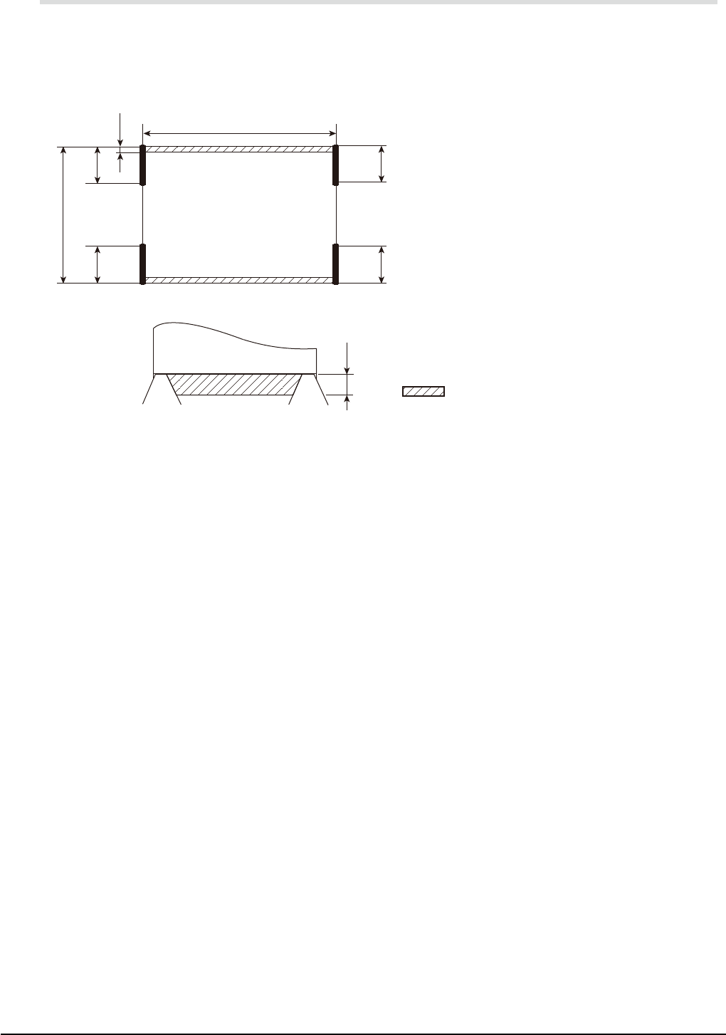
11.8 Unmountable areas on board
As illustrated below, the board includes areas where no components can be mounted due to the interference
with the conveyor rail, particularly with the board clamp claws.
Additionally, 30mm-straight zones expressed by "A" to "D" are required for the board edge to halt against
the stopper. The stopper is installed at a position of "A" to "D" depending on the machine configuration
determined by the conveyor type, board transport direction, and conveyor reference.
Rear
"Mounting not possible" range
Lmm
W
A
C
B
D
3mm
3mm
PCB suppressing PCB suppressing
Dual-stage & single-lane model
A : Right-to-left transport and front conveyor reference
B : Left-to-right transport and front conveyor reference
C : Right-to-left transport and rear conveyor reference
D : Left-to-right transport and rear conveyor reference
* Rear conveyor reference is a special order item.