ysm20r_cabpara.pdf - 第26页
32 1 1. Specications YSM20R (SESMK18400-00) v2.001 1 1 .8 Unmountable area s on board As illustrated below , the board includes areas where no components can be mounte d due to the interference with the conveyor rail, p…
31
11. Specications
YSM20R (SESMK18400-00) v2.001
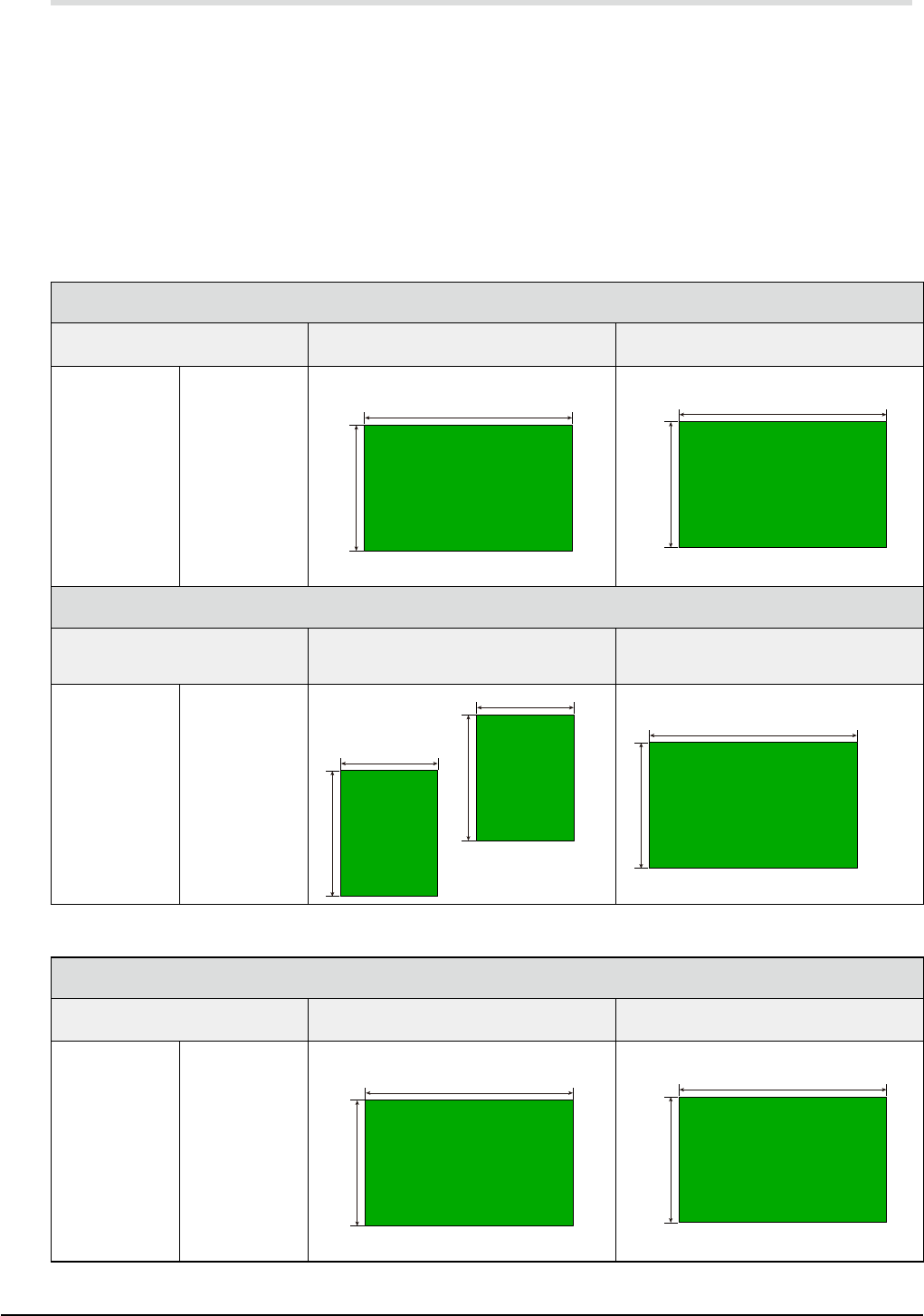
11.7 Applicable board dimensions
YSM20R-2
L size : L50
x
W50 (min.) to L810
x
W 490 (max.) [dual-stage and single lane model]
YSM20R-1
L size : L50
x
W50 (min.) to L810
x
W 490 (max.) [single lane model]
M size : L50
x
W50 (min.) to L360
x
W 490 (max.) [single lane model]
* "L" is a direction along the transport direction while "W" is a direction perpendicular to the transport.
* Maximum dimensions are illustrated below.
YSM20R-2
Single lane model ====> [SL]
Machine layout type
(See "13. References and details".)
Applicable Maximum PCB (L size) Applicable Maximum PCB (M size)
#001
#002
#003
#004
#005
#006
#007
#008
#00S
#00T
#011
#012
#013
#014
#015
#016
#017
#018
#01S
#01T
L810 (Option) / L510 (Standard)
W490
L360 (Standard)
W490
Dual-stage model ====> [DS]
Machine layout type
(See "13. References and details".)
Applicable Maximum PCB
(For dual-stage transport)
Applicable Maximum PCB
(For sigle-stage transport)
#009
#00A
#00B
#00C
#00D
#00E
#00F
#00G
#00U
#00V
#019
#01A
#01B
#01C
#01D
#01E
#01F
#01G
#01U
#01V
L380
W490
L380
W490
L810
W490
YSM20R-1
Single lane model ====> [SL]
Machine layout type
(See "13. References and details".)
Applicable Maximum PCB (L size) Applicable Maximum PCB (M size)
#001
#002
#003
#004
#005
#006
#007
#008
#10S
#10T
#011
#012
#013
#014
#015
#016
#017
#018
#11S
#11T
L810 (Option) / L510 (Standard)
W490
L360 (Standard)
W490
32
11. Specications
YSM20R (SESMK18400-00) v2.001
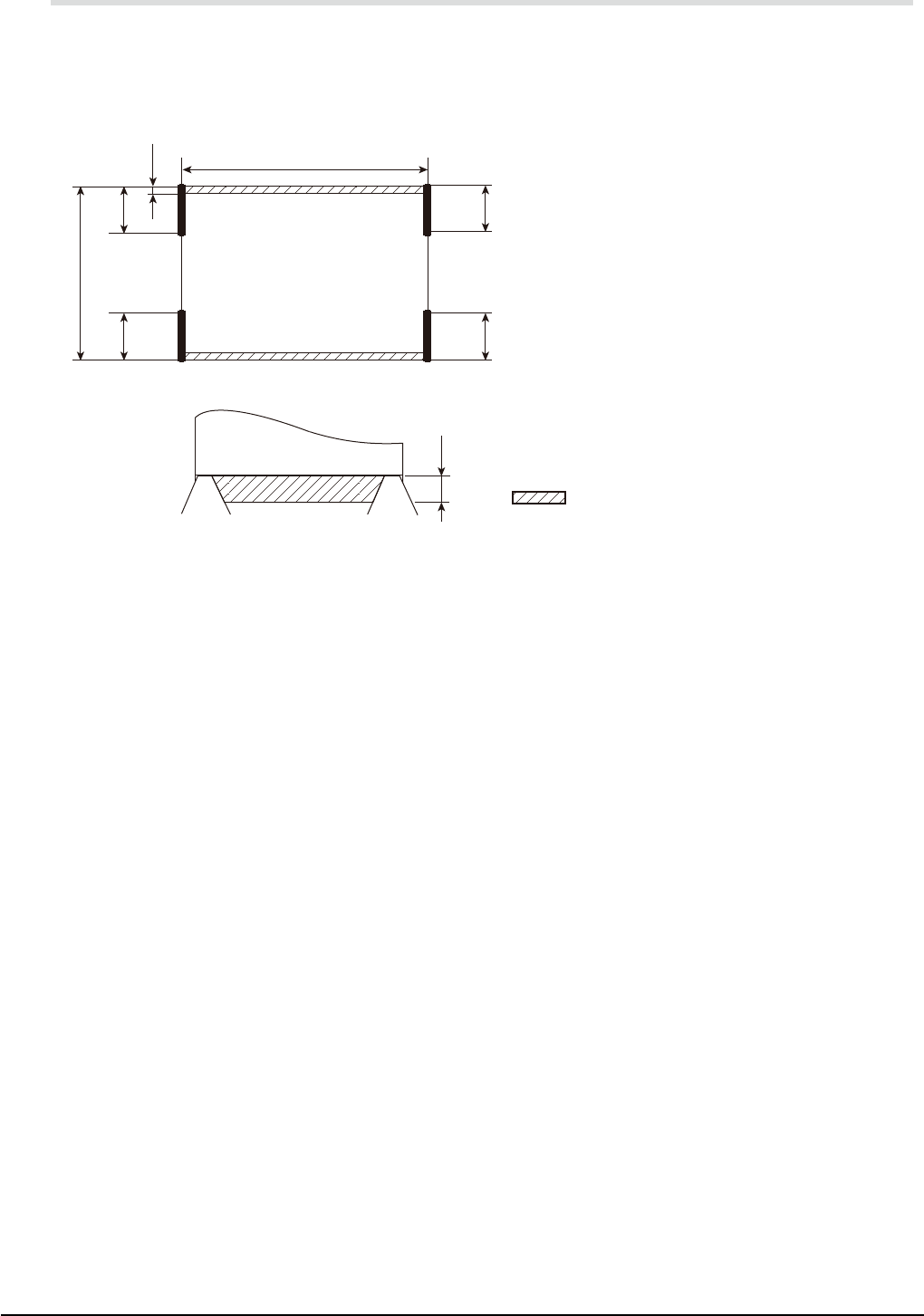
11.8 Unmountable areas on board
As illustrated below, the board includes areas where no components can be mounted due to the interference
with the conveyor rail, particularly with the board clamp claws.
Additionally, 30mm-straight zones expressed by "A" to "D" are required for the board edge to halt against
the stopper. The stopper is installed at a position of "A" to "D" depending on the machine configuration
determined by the conveyor type, board transport direction, and conveyor reference.
Rear
"Mounting not possible" range
Lmm
W
A
C
B
D
3mm
3mm
PCB suppressing PCB suppressing
Dual-stage & single-lane model
A : Right-to-left transport and front conveyor reference
B : Left-to-right transport and front conveyor reference
C : Right-to-left transport and rear conveyor reference
D : Left-to-right transport and rear conveyor reference
* Rear conveyor reference is a special order item.
33
11. Specications
YSM20R (SESMK18400-00) v2.001
11.9 Applicable board thickness
0.4 to 3.0mm
11.10 Applicable board weight
0.65kg or less per sheet
* Consult us for board weights exceeding 0.65kg.
11.11 Recommended board material
Glass fiber reinforced epoxy resin
* Consult us for other materials.
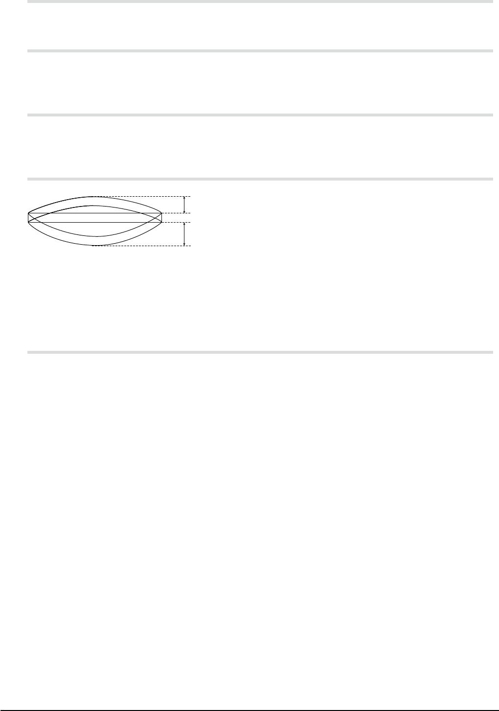
11.12 Allowable board warp
0.5mm
1.0mm
Upward warp: 0.5mm or less
Downward warp: 1.0mm or less
* Warps which exceed the above values (particularly the upward warp) may significantly reduce the
component mounting accuracy. An excessive warp may cause interference with the head, nozzle,
or camera, so use caution.
11.13 Board slits and holes
The conveyor is equipped with sensors (light transmission type) to check the position of boards being
conveyed. The position of the boards may not be detected correctly if they have slits and holes.
Consult us when using such boards.