ysm20r_cabpara.pdf - 第28页
34 1 1. Specications YSM20R (SESMK18400-00) v2.001 1 1 .14 Restric tions on mounting component s on boar ds Component height (For details about mountable component height, see below.) 3.5mm Max.30mm W direction L direct…
33
11. Specications
YSM20R (SESMK18400-00) v2.001
11.9 Applicable board thickness
0.4 to 3.0mm
11.10 Applicable board weight
0.65kg or less per sheet
* Consult us for board weights exceeding 0.65kg.
11.11 Recommended board material
Glass fiber reinforced epoxy resin
* Consult us for other materials.
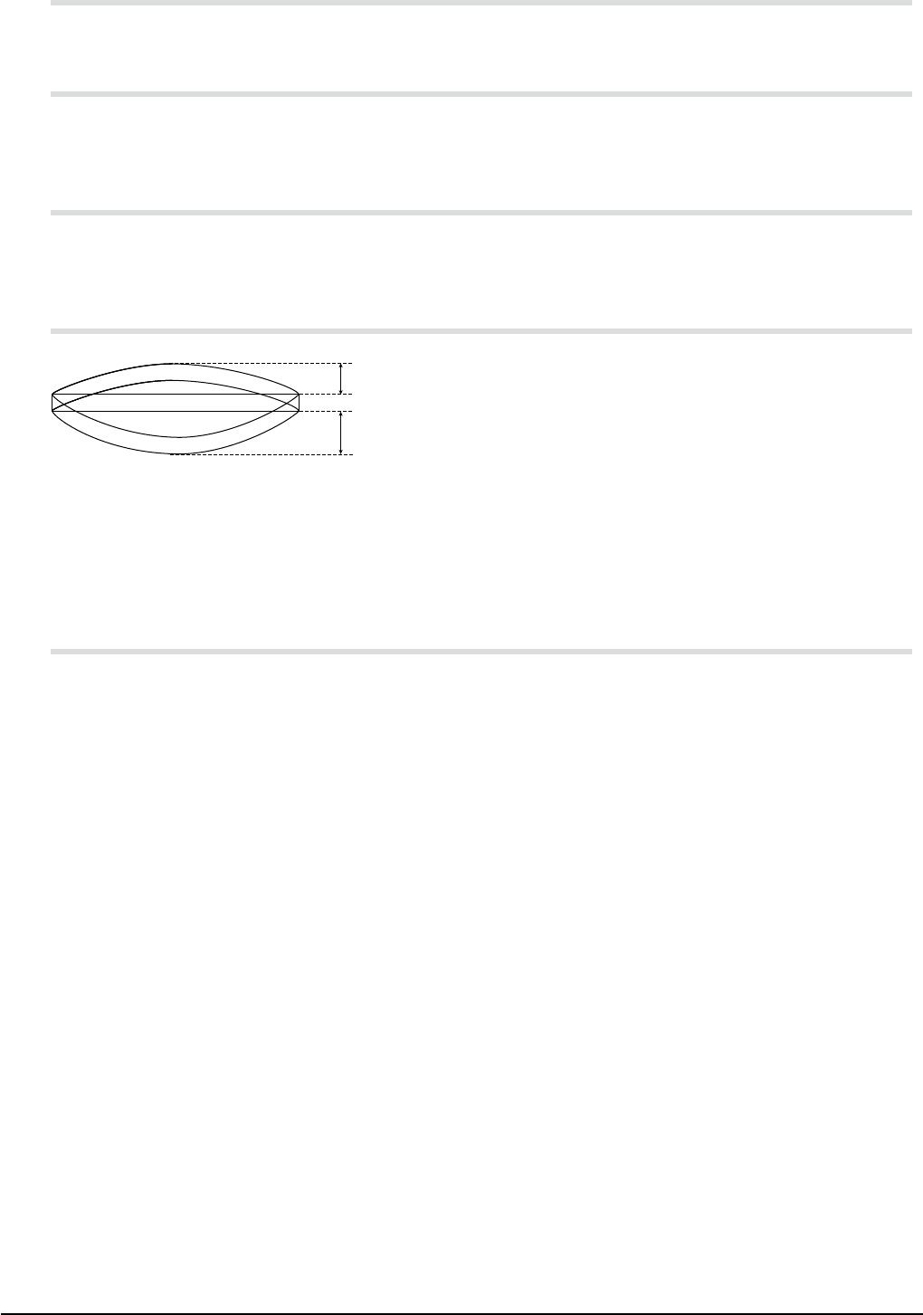
11.12 Allowable board warp
0.5mm
1.0mm
Upward warp: 0.5mm or less
Downward warp: 1.0mm or less
* Warps which exceed the above values (particularly the upward warp) may significantly reduce the
component mounting accuracy. An excessive warp may cause interference with the head, nozzle,
or camera, so use caution.
11.13 Board slits and holes
The conveyor is equipped with sensors (light transmission type) to check the position of boards being
conveyed. The position of the boards may not be detected correctly if they have slits and holes.
Consult us when using such boards.
34
11. Specications
YSM20R (SESMK18400-00) v2.001
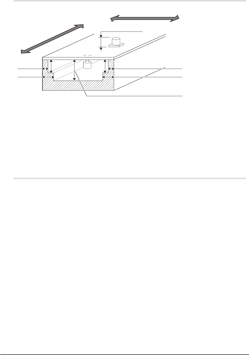
11.14 Restrictions on mounting components on boards
Component height
(For details about mountable
component height, see below.)
3.5mm
Max.30mm
W direction
L direction
Rear
Front
5.5mm
3.5mm
5.5mm
H
H
:
19mm
(Dual-stage conveyor)
17.5mm
(Single lane)
H
Upper side of board: See "11.5.1 Height of mountable components".
* No components can be placed in areas of 3mm from both ends in the board transport direction.
See also the figure in "11.8 Unmountable areas on board".
Back side of board: 30mm or less
* No components can be placed in areas of 3.5mm from both ends in the board transport direction.
No components can be mounted in the shaded areas in the above figure.
11.15 Board transport speed
50 to 500mm / sec (Speed setting can be changed.)
* The transport speed may vary depending on the board weight.
35
12. General specications
YSM20R (SESMK18400-00) v2.001
12. General specifications
12.1 Safety design
This machine conforms to the EU Machinery Directive 2006/42/EC and EMC Directive 2014/30/EU (CE
marking). However, this machine does not bear CE marking if a special order item with custom
specifications is installed. See "10.7 CE marking" for details.
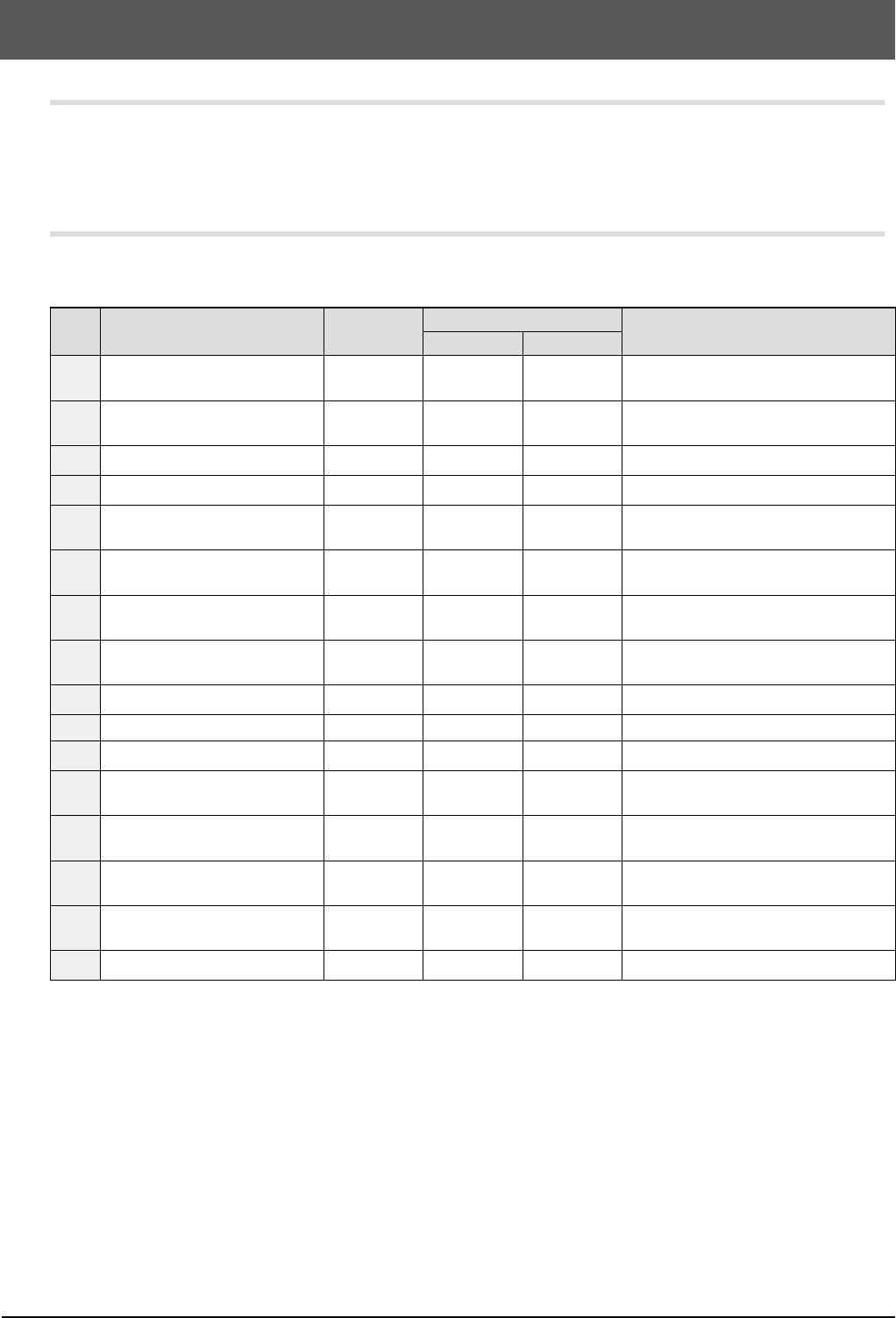
12.2 Emergency stop and error detection systems
To ensure the safety, this machine has an emergency stop system and error detection system shown in the
table below.
No. System area and item
Registration
name
Built-in
Remarks
YSM20R-2 YSM20R-1
01
Emergency stop on front
operation console
SB31
◎ ◎
Push-lock, turn-reset button
02
Emergency stop on rear
operation console
SB31
◎ ◎
Push-lock, turn-reset button
03 Front safety cover SQ101
◎ ◎
Mechanical switch with key
04 Rear safety cover SQ102
◎ ◎
Mechanical switch with key
05 Front left 32-feeder bank (*1) -
△ △
Feeder exchange carriage and ATS
docking check
06 Front right 32-feeder bank (*1) -
△ △
Feeder exchange carriage docking
check
07 Rear right 32-feeder bank (*1) -
△ △
Feeder exchange carriage and ATS
docking check
08 Rear left 32-feeder bank (*1) -
△ △
Feeder exchange carriage docking
check
09 Servo 1 group of control box -
◎
YA1, YA2, UA, PUA axis error detection
10 Servo 2 group of control box -
◎ ◎
YB1, YB2, UB, PUB axis error detection
11 Servo 3 group of control box -
◎ ◎
XA, SCA, XB, SCB axis error detection
12 Servo 4 group of control box -
△ △
AZA and AZB axis error detection, ATS
option
13 Remote servo 1 of control box -
◎
ZA1-10, RA1, RA2 (HM head) / ZA1-5,
RA1-5 (FM head) axis error detection
14 Remote servo 2 of control box -
◎ ◎
ZB1-10, RB1, RA2 (HM head) / ZB1-5,
RB1-5 (FM head) axis error detection
15 Remote servo 3 of control box -
◎ ◎
CV1-4, W1-4, ATA, ATB, AHA, AHB axis
error detection
16 Axis interference detection SQ027
◎
YA and YB axis interference detection
* Meaning of "Built-in" mark ==>
◎
: Provided,
△
: Selectable as option
*
"Registration name" is the name described in the control wiring diagram for maintenance support (YAMAHA
Support & Service Website).
* (*1) Not available when a fixed feeder plate is used.
* Other hardware-related detection errors include temperature errors, fan stop, and power supply errors.
For details, see the user’s manuals.