ysm20r_cabpara.pdf - 第31页
37 12. General specications YSM20R (SESMK18400-00) v2.001 12.5 Basic oper ation of machine The basic operation of this machine is performed wit h the buttons on the operation panel as described in the table below . Acco…
36
12. General specications
YSM20R (SESMK18400-00) v2.001
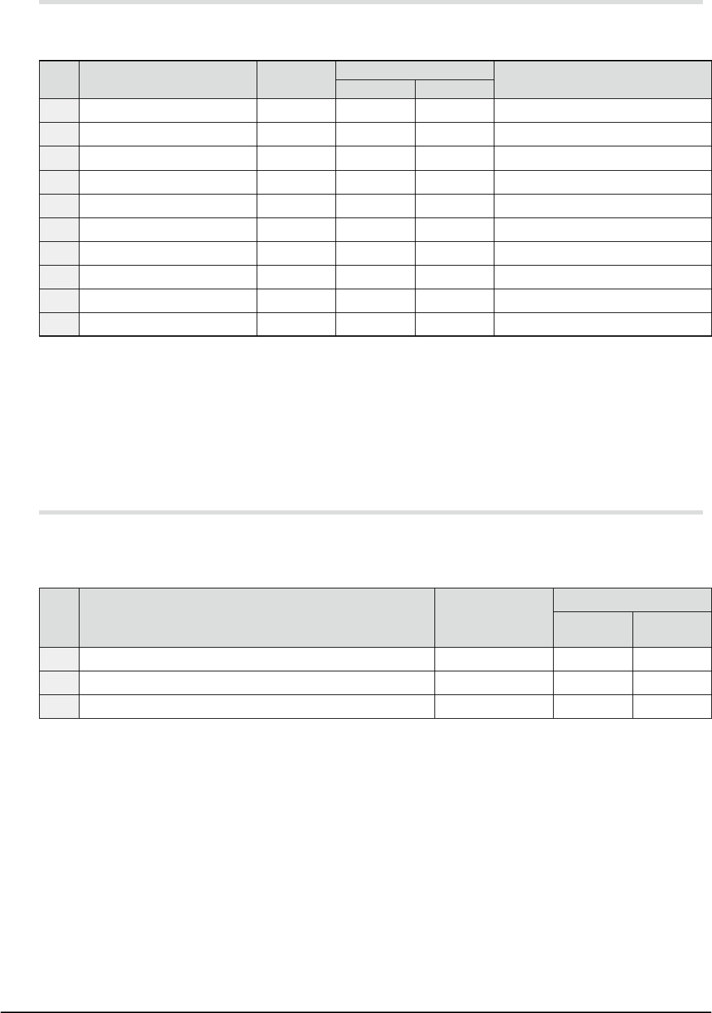
12.3 Pause (interlock) system and error detection system
To protect the machine or continue the operation, this machine as a pause system and error stop system
shown in the table below.
No. System area and item
Registration
name
Built-in
Remarks
YSM20R-2 YSM20R-1
01 Front left feeder group SQ131
◎ ◎
Check for feeder setup
02 Front right feeder group (*1) SQ132
△ △
Check for feeder setup
03 Rear right feeder group SQ133
◎ ◎
Check for feeder setup
04 Rear left feeder group (*1) SQ134
△ △
Check for feeder setup
05 Front head air pressure SP11
◎
- Air pressure drop
06 Rear head air pressure SP12
◎ ◎
Air pressure drop
07 Front-side chip dump box SQ196
◎ ◎
With or without chip dump box
08 Rear-side chip dump box SQ197
◎
- With or without chip dump box
09 Front-side shaft blow SQ191
◎ ◎
With or without nozzle
10 Rear-side shaft blow SQ192
◎
- With or without nozzle
* Meaning of "Built-in" mark ==>
◎
: Provided,
△
: Selectable as option, No mark : not available
* "Registration name" is the name described in the control wiring diagram for maintenance support
(YAMAHA Support & Service Website).
* (*1) Not available when a fixed feeder plate is used.
* Other hardware-related detection errors include temperature errors, fan stop, and power supply errors.
For details, see the user’s manuals.
12.4 Machine status indication
The status of this machine is displayed using the signal tower as described in the table below.
According to the shipment destination or the customer’s equipment specifications, the desired lighting
pattern can be selected using Lighting color pattern in "1. Machine configuration".
No. Machine status
Lighting
portion
Lighting color
General
Europe
YAMAHA
standard
01 Emergency stop status, safety cover open, CPU error, etc. Upper portion White Red
02 Pickup error, transport error, component supply run-out, etc. Middle portion Blue Yellow
03 Automatic operation is running. Lower portion Green Green
37
12. General specications
YSM20R (SESMK18400-00) v2.001
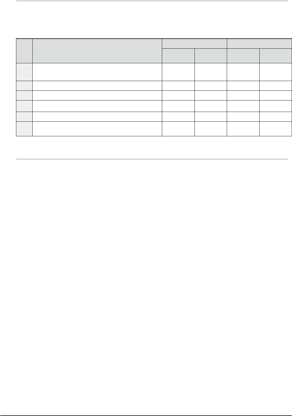
12.5 Basic operation of machine
The basic operation of this machine is performed with the buttons on the operation panel as described in the
table below.
According to the shipment destination or the customer’s equipment specifications, the desired identification
color pattern can be selected using Lighting color pattern in "1. Machine configuration".
No. Basic operation
Button name Identification color
English Chinese
General
Europe
YAMAHA
standard
01
Designation of active side on the front or rear operation
console
ACTIVE
激活
White White
02 Emergency stop status reset and servo ON READY
准备就绪
White White
03 Data reset or mounting order indexing RESET
复位
White White
04 Automatic operation start START
开始
Green Green
05 Automatic operation stop STOP
停机
White Red
06 Error lock status reset
ERROR
CLEAR
清除错误
Blue Yellow
12.6 Language used for operation screen and user’s manual
For language used for operation screens and user’s manual of this equipment, select a desired language from
English, Chinese, Korean, and Japanese.
Select the desired language using Display language in "1. Machine configuration" and Language written in
manual in "3. Arrangements / -1- Accessories".
* When installing this machine in an EU country, see "10.7 CE marking".
38
12. General specications
YSM20R (SESMK18400-00) v2.001
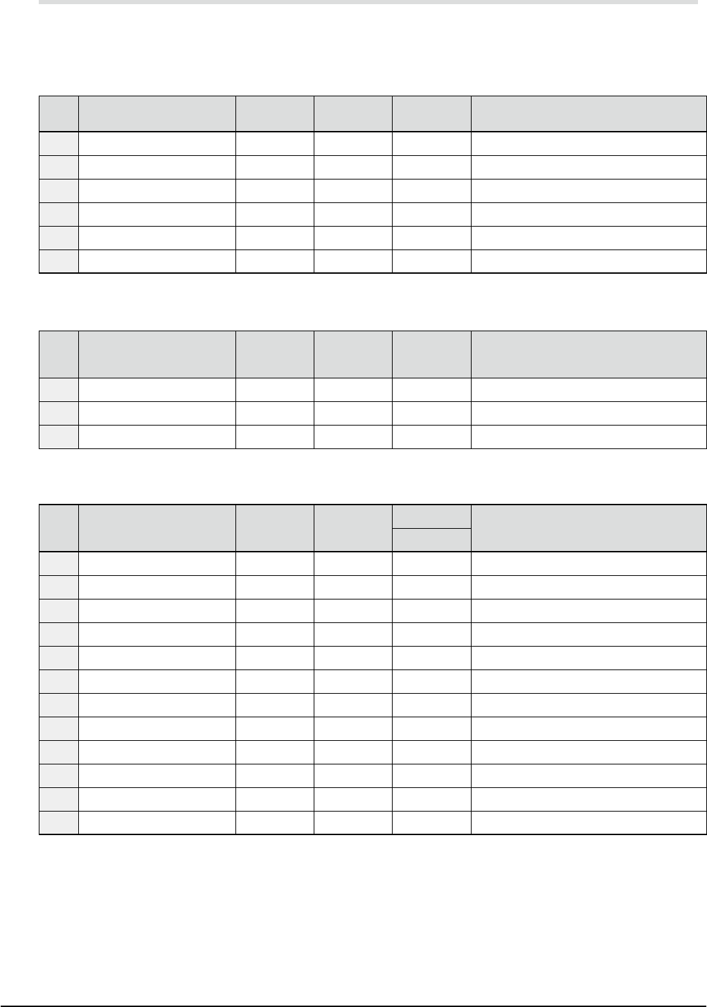
12.7 Configuration of servo control axes
According to the total number of axes and machine configuration, 16 to 48 axes are controlled by the AC
servo motors.
YSM20R-2 main unit
No. System area and item
Registration
name
Motor name Built-in Remarks
01 Frame beam A, left YA1 M01
◎
Linear motor
02 Frame beam A, right YA2 M02
◎
Linear motor
03 Frame beam B, right YB1 M03
◎
Linear motor
04 Frame beam B, left YB2 M04
◎
Linear motor
05 Frame beam A XA M05
◎
06 Frame beam B XB M06
◎
YSM20R-1 main unit
No. System area and item
Registration
name
Motor name Built-in Remarks
01 Frame beam A, right YA1 M03
◎
Linear motor
02 Frame beam A, left YA2 M04
◎
Linear motor
03 Frame beam A XA M06
◎
DS conveyor
No. System area and item
Registration
name
Motor
name
Built-in
Remarks
YSM20R-2
01 Push-up 1 PU1 M07
△
Electromagnetic brake is built-in.
02 Push-up 2 PU2 M08
△
Electromagnetic brake is built-in.
03 Table shift 1 U1 M09
△
04 Table shift 2 U2 M10
△
05 Conveyor 1 CV1 M11
△
06 Conveyor 2 CV2 M12
△
07 Conveyor 3 CV3 M13
△
08 Conveyor 4 CV4 M14
△
09 Conveyor 1 width W1 M15
△
10 Conveyor 2 width W2 M16
△
11 Conveyor 3 width W3 M17
△
12 Conveyor 4 width W4 M18
△