ysm20r_cabpara.pdf - 第33页
39 12. General specications YSM20R (SESMK18400-00) v2.001 SL co nveyor No. System area and it em Registrat ion name Motor name Built-in Remarks YSM20R-2 YSM20R-1 01 Push-up 1 PU1 M08 △ ◎ Electromagnetic brake is built-i…
38
12. General specications
YSM20R (SESMK18400-00) v2.001
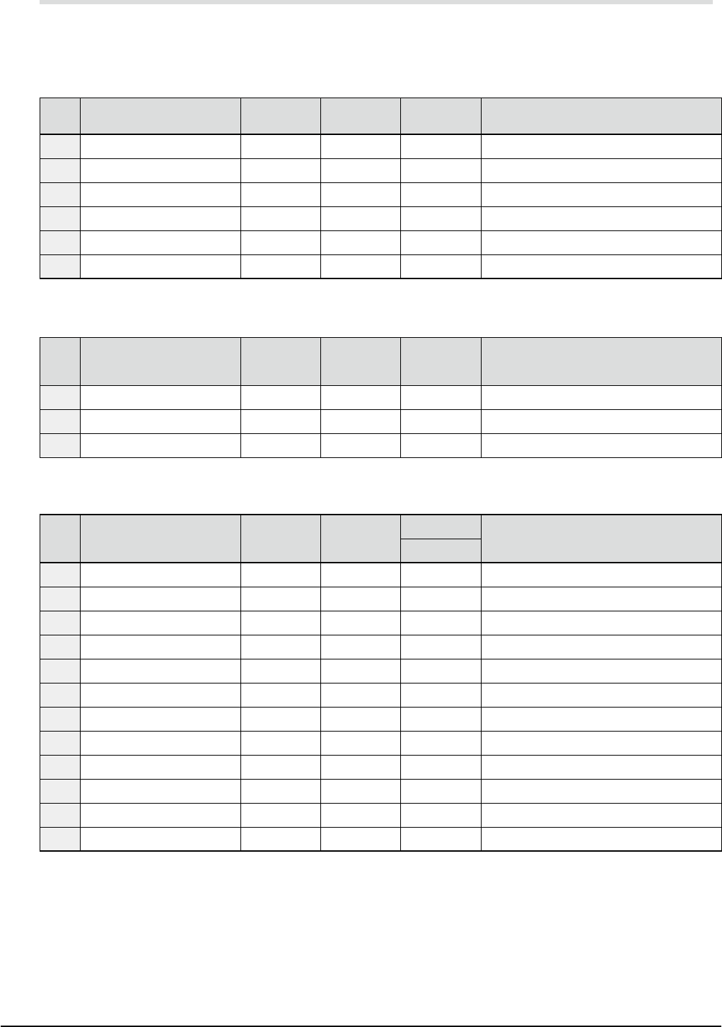
12.7 Configuration of servo control axes
According to the total number of axes and machine configuration, 16 to 48 axes are controlled by the AC
servo motors.
YSM20R-2 main unit
No. System area and item
Registration
name
Motor name Built-in Remarks
01 Frame beam A, left YA1 M01
◎
Linear motor
02 Frame beam A, right YA2 M02
◎
Linear motor
03 Frame beam B, right YB1 M03
◎
Linear motor
04 Frame beam B, left YB2 M04
◎
Linear motor
05 Frame beam A XA M05
◎
06 Frame beam B XB M06
◎
YSM20R-1 main unit
No. System area and item
Registration
name
Motor name Built-in Remarks
01 Frame beam A, right YA1 M03
◎
Linear motor
02 Frame beam A, left YA2 M04
◎
Linear motor
03 Frame beam A XA M06
◎
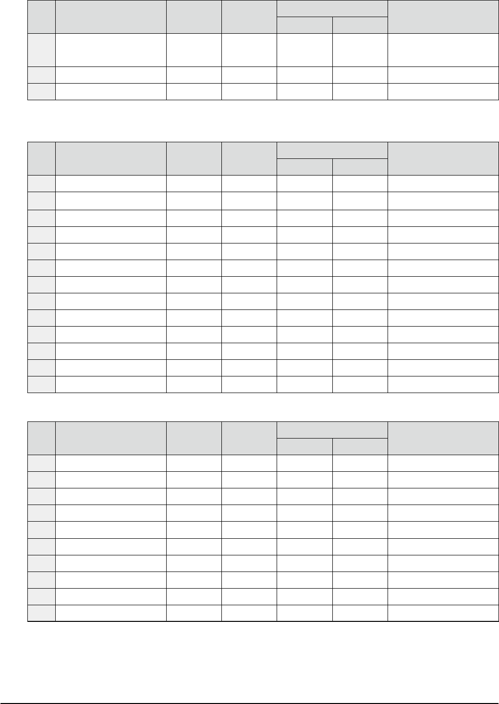
DS conveyor
No. System area and item
Registration
name
Motor
name
Built-in
Remarks
YSM20R-2
01 Push-up 1 PU1 M07
△
Electromagnetic brake is built-in.
02 Push-up 2 PU2 M08
△
Electromagnetic brake is built-in.
03 Table shift 1 U1 M09
△
04 Table shift 2 U2 M10
△
05 Conveyor 1 CV1 M11
△
06 Conveyor 2 CV2 M12
△
07 Conveyor 3 CV3 M13
△
08 Conveyor 4 CV4 M14
△
09 Conveyor 1 width W1 M15
△
10 Conveyor 2 width W2 M16
△
11 Conveyor 3 width W3 M17
△
12 Conveyor 4 width W4 M18
△
39
12. General specications
YSM20R (SESMK18400-00) v2.001
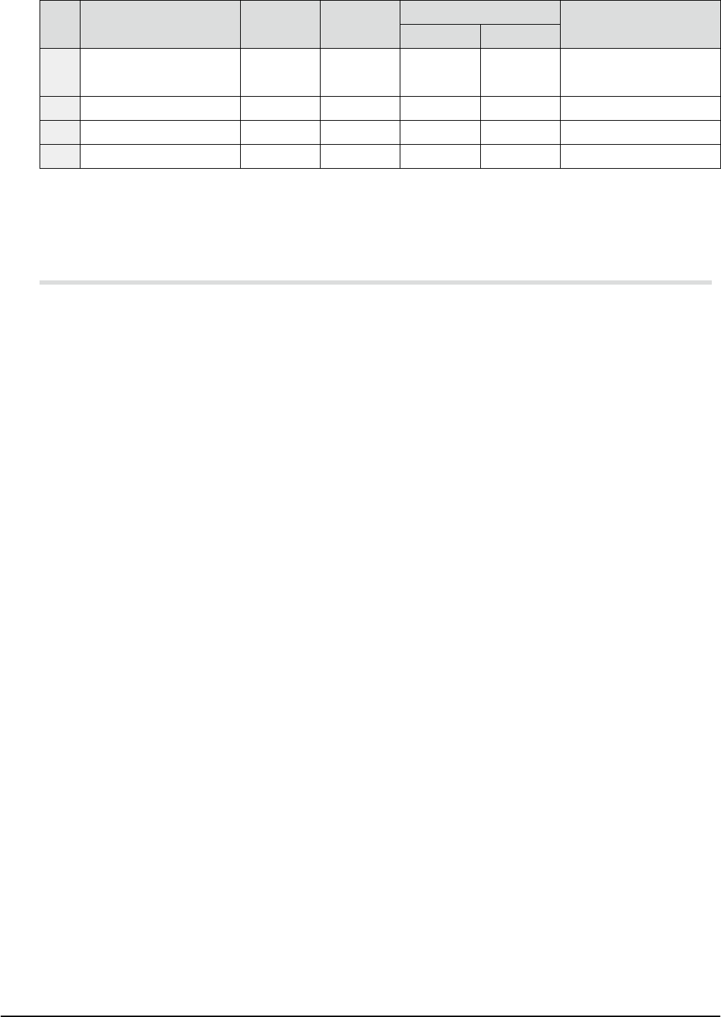
SL conveyor
No. System area and item
Registration
name
Motor
name
Built-in
Remarks
YSM20R-2 YSM20R-1
01 Push-up 1 PU1 M08
△ ◎
Electromagnetic brake is
built-in.
02 Conveyor 1 CV1 M11
△ ◎
03 Conveyor 1 width W1 M15
△ ◎
HM head
No. System area and item
Registration
name
Motor
name
Built-in
Remarks
YSM20R-2 YSM20R-1
01 HM head 1 up/down ZA1 / ZB1 M31
△ △
Linear motor
02 HM head 2 up/down ZA2 / ZB2 M32
△ △
Linear motor
03 HM head 3 up/down ZA3 / ZB3 M33
△ △
Linear motor
04 HM head 4 up/down ZA4 / ZB4 M34
△ △
Linear motor
05 HM head 5 up/down ZA5 / ZB5 M35
△ △
Linear motor
06 HM head 6 up/down ZA6 / ZB6 M36
△ △
Linear motor
07 HM head 7 up/down ZA7 / ZB7 M37
△ △
Linear motor
08 HM head 8 up/down ZA8 / ZB8 M38
△ △
Linear motor
09 HM head 9 up/down ZA9 / ZB9 M39
△ △
Linear motor
10 HM head 10 up/down ZA10 / ZB10 M40
△ △
Linear motor
11 HM head 1 rotation RA1 / RB1 M41
△ △
12 HM head 2 rotation RA2 / RB2 M42
△ △
13 HM head Scan SCA / SCB M43
△ △
Linear motor
FMhead
No. System area and item
Registration
name
Motor
name
Built-in
Remarks
YSM20R-2 YSM20R-1
01 FM head 1 up/down ZA1 / ZB1 M51
△ △
02 FM head 2 up/down ZA2 / ZB2 M52
△ △
03 FM head 3 up/down ZA3 / ZB3 M53
△ △
04 FM head 4 up/down ZA4 / ZB4 M54
△ △
05 FM head 5 up/down ZA5 / ZB5 M55
△ △
06 FM head 1 rotation RA1 / RB1 M56
△ △
07 FM head 2 rotation RA2 / RB2 M57
△ △
08 FM head 3 rotation RA3 / RB3 M58
△ △
09 FM head 4 rotation RA4 / RB4 M59
△ △
10 FM head 5 rotation RA5 / RB5 M60
△ △
40
12. General specications
YSM20R (SESMK18400-00) v2.001
cATS10 / sATS30 / sATS30NS
No. System area and item
Registration
name
Motor
name
Built-in
Remarks
YSM20R-2 YSM20R-1
01 rack up/down AZ1 / AZ2 M71
△ △
Electromagnetic brake is
built-in.
02
Table back / forth
AT1 / AT2 M72
△ △
03
Hook back / forth
AH1 / AH2 M73
△ △
04
Supply hook back / forth
AHS1 / AHS2 M74
△ △
* Meaning of "Built-in" mark ==>
◎
: Provided,
△
: Selectable as option, No mark : not available
* "Motor name" is the name described in the control wiring diagram for maintenance support
(YAMAHA Support & Service Website).
12.8 Configuration of other motors
To cool the control box, motors, and cameras, FAN motors are installed at appropriate positions.