ysm20r_cabpara.pdf - 第37页
43 12. General specications YSM20R (SESMK18400-00) v2.001 12.9.4 Multi-view camera with coplanari ty check er (option) Item Remarks System Multi-view c amera with coplanar ity checker * Component r ecognition perf orman…
42
12. General specications
YSM20R (SESMK18400-00) v2.001
12.9.2 Scan camera (standard for HM head)
Item Remarks
System Scan camera (with coaxial lighting)
Camera position HM head Bottom side of head
Field of view 18 x 18mm, Width 6mm (Side)
Application Component recognition
Maximum recognizable
size
12 x 12mm * For Type SV, 8 x 8 mm
Minimum recognizable
size
0201 square chip components ("mm" size)
Allowable component
height
6.5mm
Recognizable lead pitch 0.4mm or more
12.9.3 Multi-view camera (standard for FM head / option for HM head)
Item Remarks
System
Multi-view camera
* In addition to detecting whether ball electrodes exist or not, the camera also detects whether
they are good or not by side lighting provided as standard.
Camera position
Front right side of conveyor system
Front right side of rear conveyor system
Field of view 50mm
Application Component recognition
Maximum recognizable
size
55 x 100mm
* Consult us for odd-form components such as long connectors.
* Recognition of components larger than 45mm sq. is available by Split recognition.
Minimum recognizable
size
03015 square chip component ("mm" size)
Allowable component
height
HM head 15mm or less
FM head 28mm or less
Recognizable lead pitch 0.3mm or more
Ball electrode size for
present/absent judgment
φ
0.1mm or more
Ball electrode size for
pass/fail judgment
φ
0.15mm or more
43
12. General specications
YSM20R (SESMK18400-00) v2.001
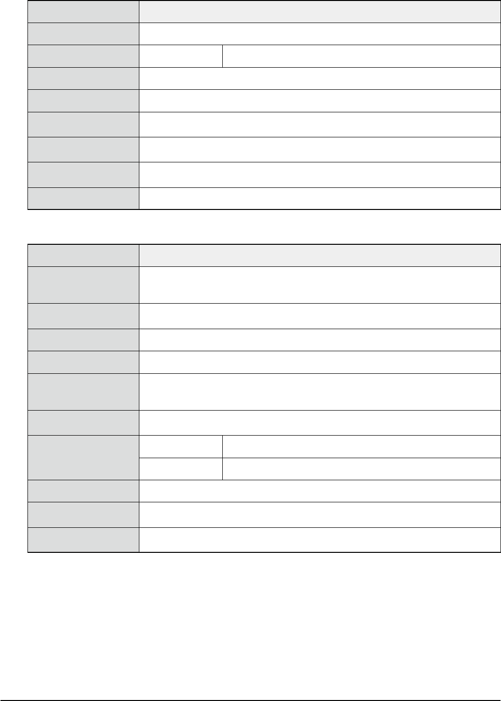
12.9.4 Multi-view camera with coplanarity checker (option)
Item Remarks
System
Multi-view camera with coplanarity checker
* Component recognition performance is the same as that of the multi-view camera
(in 12.9.3) excep for the coplanarity checker function.
Camera position Installed in the multi-view camera for component recognition
Field of view 50mm
Application
Detection of variations in the height direction of multiple row lead electrodes and ball
electrodes, that is, the detection of lead coplanarity and linearity. Also called lead float
inspection.
Maximum recognizable
size
45 x 45mm
Allowable component
height
HM head 15mm or less
FM head 28mm or less
Coplanrity detection
accuracy
± 0.025mm
Recognizable lead pitch 0.3mm or more
Recognizable lead width 0.12mm or more
Recognizable ball
electrode
φ
0.25mm or more
12.9.5 Side-view camera
Item Remarks
System Side-view camera
Camera position
HM head Installed in the scan camera
FM head Bottom side of head
Application
Front and back side check for lead components (mini-mold transistors, two-terminal diodes,
etc.) with 1.2mm or less thickness
Pickup error detection, soiled nozzle detection, component release check
Maximum recognizable
size
3.2 x 3.2mm
Allowable component
height
1.2mm or less

44
12. General specications
YSM20R (SESMK18400-00) v2.001
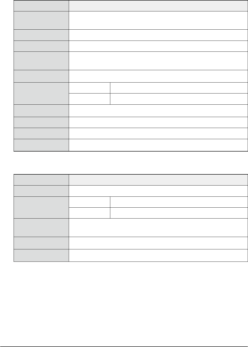
12.9.6 Smart recognition
Item Remarks
System Applicable component size
Application
This function is intended to provide a recognition algorism with high versatility and robustness.
A component shape model is created from the component image that has been captured.
The positioning of the component is performed using this component shape model.
This allows the recognition of components that are impossible or difficult to define with existing
algorisms.
Recognition accuracy (3σ) ± 0.03mm, ± 1 deg.
Applicable component
size
1.0 x 0.5mm to 45 x 45mm