ysm20r_cabpara.pdf - 第38页
44 12. General specications YSM20R (SESMK18400-00) v2.001 12.9.6 Smar t reco gnition Item Remarks System Applicable componen t size Application This function is intended to pr ovide a r ecognition algorism w ith high ve…
43
12. General specications
YSM20R (SESMK18400-00) v2.001
12.9.4 Multi-view camera with coplanarity checker (option)
Item Remarks
System
Multi-view camera with coplanarity checker
* Component recognition performance is the same as that of the multi-view camera
(in 12.9.3) excep for the coplanarity checker function.
Camera position Installed in the multi-view camera for component recognition
Field of view 50mm
Application
Detection of variations in the height direction of multiple row lead electrodes and ball
electrodes, that is, the detection of lead coplanarity and linearity. Also called lead float
inspection.
Maximum recognizable
size
45 x 45mm
Allowable component
height
HM head 15mm or less
FM head 28mm or less
Coplanrity detection
accuracy
± 0.025mm
Recognizable lead pitch 0.3mm or more
Recognizable lead width 0.12mm or more
Recognizable ball
electrode
φ
0.25mm or more
12.9.5 Side-view camera
Item Remarks
System Side-view camera
Camera position
HM head Installed in the scan camera
FM head Bottom side of head
Application
Front and back side check for lead components (mini-mold transistors, two-terminal diodes,
etc.) with 1.2mm or less thickness
Pickup error detection, soiled nozzle detection, component release check
Maximum recognizable
size
3.2 x 3.2mm
Allowable component
height
1.2mm or less

44
12. General specications
YSM20R (SESMK18400-00) v2.001
12.9.6 Smart recognition
Item Remarks
System Applicable component size
Application
This function is intended to provide a recognition algorism with high versatility and robustness.
A component shape model is created from the component image that has been captured.
The positioning of the component is performed using this component shape model.
This allows the recognition of components that are impossible or difficult to define with existing
algorisms.
Recognition accuracy (3σ) ± 0.03mm, ± 1 deg.
Applicable component
size
1.0 x 0.5mm to 45 x 45mm
45
12. General specications
YSM20R (SESMK18400-00) v2.001
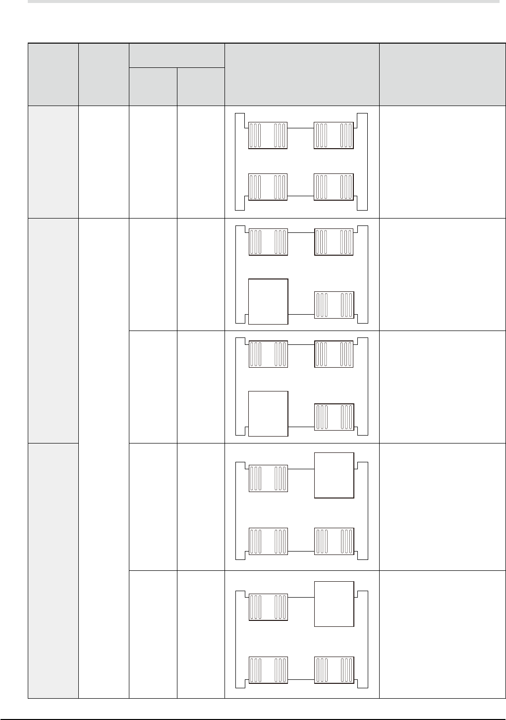
12.10 Feeder bank configuration
The feeder bank configuration of this machine can be selected from those shown in the table below.
Select using Feeder Bank in "1. Machine Configuration".
Configura-
tion
Number of
8mm wide
tape
feeders
Layout
layout illustration Details
YSM20R-2 YSM20R-1
F64 / 64 128
#001
#011
#009
#019
#00H
#01H
#101
#111
Front
Rear
1
32
33
64
164
133
132
101
32
32 32
32
Front right : 32-feeder exchange carriage
Front left : 32-feeder exchange carriage
Rear right : 32-feeder exchange carriage
Rear left : 32-feeder exchange carriage
F32 / 64
96
#002
#012
#00A
#01A
#00J
#01J
#102
#112
Front
Rear
33
64
164
133
32
132
101
32
32
cATS10
Front right : 32-feeder exchange carriage
Front left : CATS10
Rear right : 32-feeder exchange carriage
Rear left : 32-feeder exchange carriage
#005
#015
#00D
#01D
#00M
#01M
#105
#115
Front
Rear
33
64
164
133
32
132
101
32
32
sATS30
Front right : 32-feeder exchange carriage
Front left : sATS30 or sATS30NS
Rear right : 32-feeder exchange carriage
Rear left : 32-feeder exchange carriage
F64 / 32
#003
#013
#00B
#01B
#00K
#01K
#103
#113
Front
Rear
1
32
33
64
164
133
32
32
32
cATS10
Front right : 32-feeder exchange carriage
Front left : 32-feeder exchange carriage
Rear right : CATS10
Rear left : 32-feeder exchange carriage
#006
#016
#00E
#01E
#00N
#01N
#106
#116
Front
Rear
1
32
33
64
164
133
32
32
32
sATS30
Front right : 32-feeder exchange carriage
Front left : 32-feeder exchange carriage
Rear right : sATS30 or sATS30NS
Rear left : 32-feeder exchange carriage