ysm20r_cabpara.pdf - 第45页
51 12. General specications YSM20R (SESMK18400-00) v2.001 12.12. 2 Machine-to-machine signal sp ecifications (between this machine and re-process machine) * Previous Interfac e According to the operating conditions, suc…
50
12. General specications
YSM20R (SESMK18400-00) v2.001
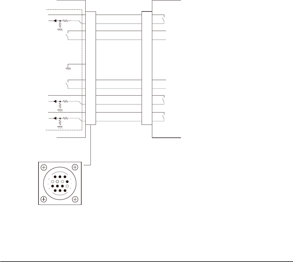
[GATE IN] : When this signal turns ON (conducts), this machine judges that the board unloading is
requested from the post-process machine and so unloads the board if the work of this machine has
been completed. The post-process machine output is a relay contact
(dry contact : no-voltage circuit).
[BUSY IN] : This input signal informs this machine that the post-process machine is loading a board.
The post-process machine output is a relay contact (dry contact: no-voltage circuit).
[BA OUT] : This output signal informs the post-process machine that this machine is ready to unload a
board.
[UR OUT] : This output signal informs the post-process machine that this machine is running in automatic
mode.
[LR IN] : This input signal informs this machine that the post-process machine is running in automatic
mode. The post-process machine output is a relay contact (dry contact : no-voltage circuit).
[LE IN] : This signal is used for Advanced (extended) GATE 2 signal specifications when the "inter-machine
board standby function" used between mounters is enabled. This input signal informs this machine
that a board is at the standby position between this machine and post-process machine.
The post-process machine output is a relay contact (dry contact: no-voltage circuit).
The cable with a yellow marking put close to the connector should be used for the machine-to-
machine cable.
Machine-to-machine signal specifications (between this machine and post-process machine)
* Next Interface
1
2
3
4
5
6
7
8
9
10
11
12
13
14
PNP input
PNP input
DC+24V
DC+24V
PNP input
DC+24V
Relay input
Relay input
Relay input
Relay input
Relay input
Input
Input
I/O BOARD
GND
14
11
12
7
4
8
3
1
Next Interface on this machine
Previous Interface on post-process machine
Next Interface connector
AMP: 206043-1
(Receptacle 14 pins)
51
12. General specications
YSM20R (SESMK18400-00) v2.001
12.12.2
Machine-to-machine signal specifications
(between this machine and re-process machine)
* Previous Interface
According to the operating conditions, such as machine combination and signal cable selection, make
appropriate selections from the table shown below.
These specifications must match the selected settings in "12.12.1 Machine-to-machine signal specifications"
(between this machine and post-process machine: Next interface).
* When connecting to other company’s machine, the customer shall be held responsible for maintenance of
the functions related to other company’s machine.
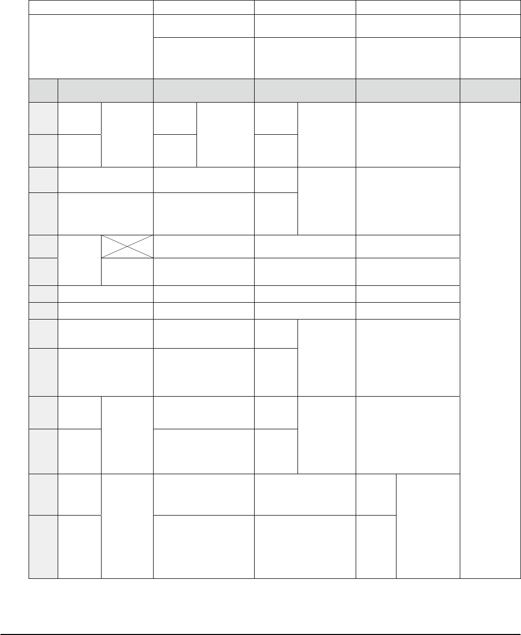
Selection
Next interface Connector on
this machine AMP: 206043-1
(Receptacle, 14 pins)
GATE signal
specifications
ADVANCED (extended)
GATE specifications
ADVANCED (extended)
GATE 2 specifications
SMEMA signal
specifications
YAMAHA YV series or
earlier (YV or earlier)
and other company’s
machine
YAMAHA X series or
later
(X / Xg / YG / YS)
YAMAHA YS series (YS)
or later *1
SMEMA signal
compatible
machine
Pin
No
Class Signal name Signal name Signal name Signal name
1
Relay
contact
output
Conducted
/ Closed
when
turned ON.
GATE
OUT
(output)
Board
unloading
request signal
output to the
pre-process
machine
BUSY
OUT
(output)
Status signal
output showing
that this
machine is
loading the
board.
Same as left
SMEMA
specifications
2
Relay
contact
output
GATE
OUT
(output)
BUSY
OUT
(output)
3 DC +24V Not used.
BA IN
(com)
Status signal
input showing
that the
pre-process
machine is ready
to unload the
board.
Same as left
4
PNP input
(Judged as ON when
the voltage is +24V.)
Not used.
BA IN
(input)
5
ncorrect
connection
prevention
function
application
Dedicated to mating
designation (Receivable)
Dedicated to mating
designation (Receivable)
Dedicated to mating
designation (Receivable)
6
Key plug
inserted.
Dedicated to mating
designation (Blocked)
Dedicated to mating
designation (Blocked)
Dedicated to mating
designation (Blocked)
7 Reserved. Reserved. Reserved. Reserved.
8 Reserved. Reserved. Reserved. Reserved.
9 DC +24V Not used.
UR IN
(com)
Status signal
input showing
that the
pre-process
machine is
running in the
automatic
operation mode.
Same as left.
10
PNP input
(Judged as ON when
the voltage is +24V.)
Not used.
UR IN
(input)
11
Relay
contact
output
Conducted
/ Closed
when
turned ON.
Not used.
LR OUT
(output)
Status signal
output showing
that this
machine is
running in the
automatic
operation
mode.
Same as left.
12
Relay
contact
output
Not used.
LR OUT
(output)
13
Relay
contact
output
Conducted
/ Closed
when
turned ON.
Not used. Not used.
LE OUT
or
LS OUT
(output)
Machine-to-
machine board
standby status
signal output to
the pre-process
machine or board
carry-in priority
lane selection
signal output
during dual-lane
operation
14
Relay
contact
output
Not used. Not used.
LE OUT
or
LS OUT
(output)
*1 : The YS / YG series mounters have already been applicable to the ADVANCED GATE 2 specifications
from the machines shipped in November, 2009. When connecting the YS / YG series mounter shipped
before this date to the line, the machine (except for YS24) needs to be modified.
52
12. General specications
YSM20R (SESMK18400-00) v2.001
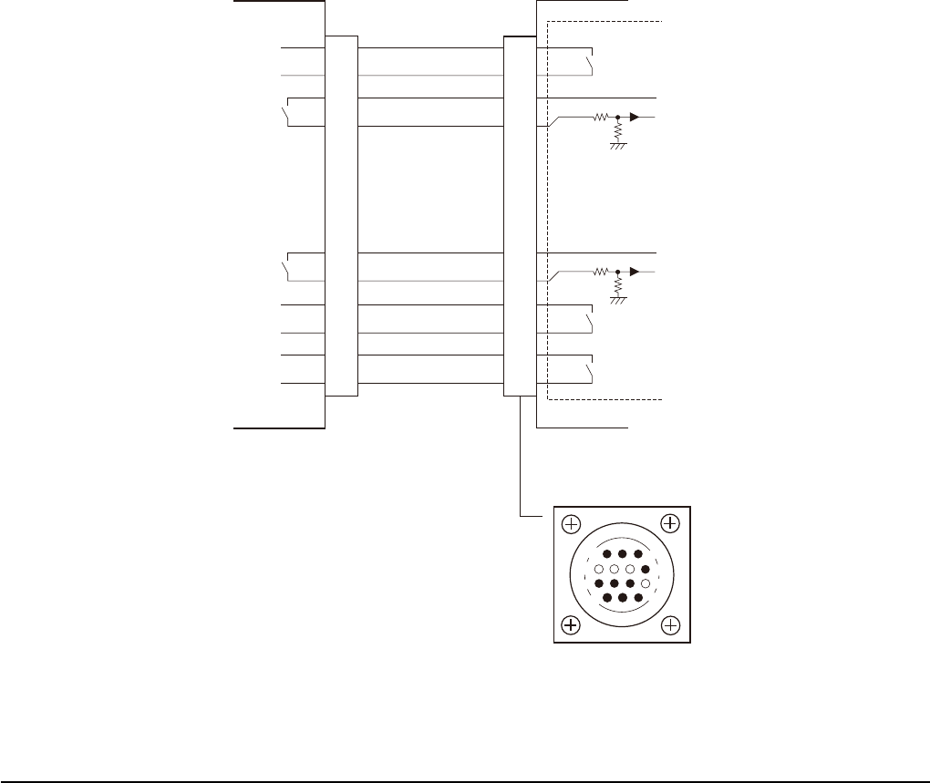
[GATE OUT] : When this machine is ready for operation, it outputs this board unloading request ON
(conduct) signal to the pre-process machine.
[BUSY OUT] : This output signal informs the pre-process machine that this machine is loading a board.
[BA IN] : This input signal informs this machine that the pre-process machine is ready to unload a board.
The pre-process machine output is a relay contact (dry contact : no-voltage circuit).
[UR IN] : This input signal informs this machine that the pre-process machine is running in automatic mode.
The pre-process machine output is a relay contact (dry contact: no-voltage circuit).
[LR OUT] : This output signal informs the pre-process machine that this machine is running in automatic
mode.
[LE OUT] : This signal is used for the Advanced (extended) GATE 2 specifications when the "inter-machine
board standby function" used between mounters is enabled. This output signal informs the pre-
process machine that a board is at the standby position between this machine and pre-process
machine. The cable with a yellow marking put close to the connector should be used for the
machine-to-machine cable.
[LS OUT] : This signal is used for the Advanced (extended) GATE 2 signal specifications only when the
"priority lane signal output" setting is enabled.
When using the dual-lane, this output signal is used to select the priority lane on the pre-process
machine that unloads the next board. (Example of pre-process machine: dual-lane branching
conveyors, solder printers, etc.) The cable with a yellow marking put close to the connector should
be used for the machine-to-machine cable.
Machine-to-machine signal specifications (between this machine and pre-process machine)
* Previous Interface
1
2
3
4
5
6
7
8
9
10
11
12
13
14
7
12
4
8
1
14
11
3
Relay output
Relay output
DC+24V
DC+24V
PNP input
PNP input
Input
Relay output
Relay output
Input
Relay output
Input
I/O BOARD
Previous Interface on this machineNext Interface on pre-process machine
Previous Interface connector
AMP: 206043-1
(Receptacle 14 pins)