A10011-ASM-T53-EN-Spec-TX-micron-DMS - 第7页
7 Machine performance Placement head types SIPLACE S peedS tar (C&P20 M2) SIPLACE MultiS t ar (CPP M) Placement performanc e The placement performance is influ enced by the different head c ombinations and head posit…
6
SIPLACE TX micron
Machine description
The latest generation of
SIPLACE placement mod-
ules set placement perfor-
mance, floorspace
performance and placement
accuracy records.
The innovative high-end
placement platform
SIPLACE TX micron
achieves new benchmarks in
placement performance and
productivity per area. The
compact design of the
SIPLACE TX micron sup-
ports precise scaling of line
performance in small steps.
The SIPLACE TX micron
placement machines are
available in three different
variants and two different
accuracy classes:
• SIPLACE TX2 micron
(588502)
• SIPLACE TX2i micron
(588500)
• SIPLACE TX2i micron 15
(588515)
Each gantry has one place-
ment head. The
SIPLACE TX micron sup-
ports two accuracy classes
for enhanced placement
accuracy, these being for 20/
25 µm or 25/15 µm. A sepa-
rate machine type is avail-
able for placement accuracy
of up to 15 µm.
Maximum accuracy
To achieve maximum accu-
racy, the
SIPLACE TX micron place-
ment machines are equipped
with high resolution scales
on the main axes and the
C&P20 M2 head. A highly
rigid PCB conveyor and an
additional fiducial rail are
also used.
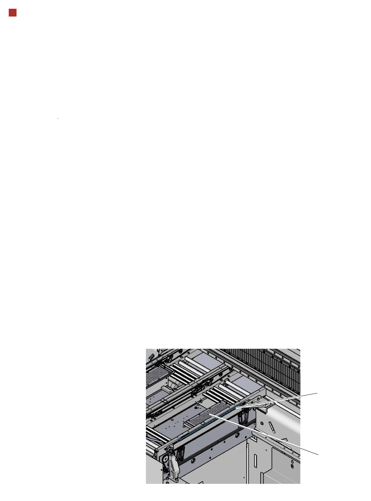
To reach placement accu-
racy of 15 µm, the boards are
placed "close to the roots",
with the help of a mechanical
stabilizer (vacuum tool).
The SIPLACE TX micron
covers the entire range of
common components with
only two placement heads.
The ideal addition to the high
speed SIPLACE SpeedStar
is the SIPLACE Multistar
placement head.
The user enjoys a board
conveyor with flexible
SIPLACE dual conveyor.
Vacuum tool
Fiducial rail

7
Machine performance
Placement head types SIPLACE SpeedStar (C&P20 M2)
SIPLACE MultiStar (CPP M)
Placement performance
The placement performance is influenced by the different head combinations and head positions, plus the con-
veyor configurations. Individual options and customized applications also influence the placement perfor-
mance. On request, ASM can calculate the actual performance of your product on your machine configuration.
IPC value [components/h]
Conducted with 0402 components, in accordance with the layout of the IPC 9850 standard of Association Con-
necting Electronics Industries.
SIPLACE benchmark value [components/h]
The SIPLACE benchmark value is measured during the machine acceptance tests. It corresponds to the condi-
tions set out in the ASM scope of service and supply.
SIPLACE TX2i micron placement
machine
Placement area IPC value Benchmark value
Placement accuracy 25 µm (3σ) C&P20 M2 / C&P20 M2 62,500 78,000
CPP M_L / CPP M_L 43,000 48,000
C&P20 M2 / CPP M_L 52,500 62,500
Placement accuracy 20 µm (3σ) C&P20 M2 / C&P20 M2 56,000 71,000
CPP M_L / CPP M_L 39,500 47,000
C&P20 M2 / CPP M_L 47,500 59,000
Placement accuracy 15 µm (3σ) C&P20 M2 / C&P20 M2 -- 64,000
SIPLACE TX2 micron placement
machine
Placement area IPC value Benchmark value
Placement accuracy 25 µm (3σ) C&P20 M2 / C&P20 M2 61,000 75,000
CPP M_L / CPP M_L 40,000 46,500
CPP M_H / CPP M_H 38,000 44,500
C&P20 M2 / CPP M_L 50,000 60,500
C&P20 M2 / CPP M_H 49,000 59,500
Placement accuracy 20 µm (3σ) C&P20 M2 / C&P20 M2 54,500 68,500
CPP M_L / CPP M_L 36,500 44,000
CPP M_H / CPP M_H 35,000 42,000
C&P20 M2 / CPP M_L 45,500 56,000
C&P20 M2 / CPP M_H 44,500 55,000
Placement accuracy 15 µm (3σ) C&P20 M2 / C&P20 M2 -- 61,500
CPP M_H = Multistar CPP M in high assembly position
CPP M_L = Multistar CPP M in low assembly position
8
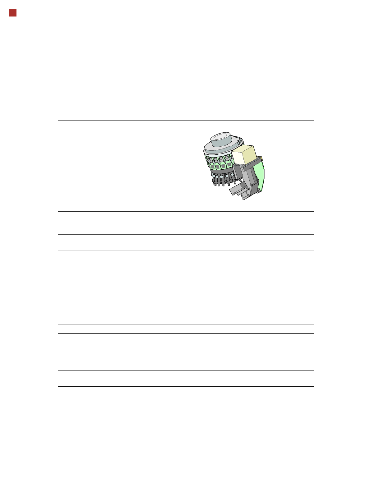
Placement heads
SIPLACE SpeedStar (C&P20 M2)
SIPLACE SpeedStar (C&P20 M2)
With component
camera type 48
(Standard)
With component
camera type 49
(Optional)
Component range
a
a) Please note that the placeable component range is also affected by the pad geometry, the customer-
specific standards, the component packaging tolerances and the component tolerances.
0.12 mm x 0.12 (0201 metric) to 2220, Melf, SOT, SOD, Bare-
Die, Flip-Chip
Component spec.
Max. height
Min. lead pitch
Min. lead width
Min. ball pitch
Min. ball diameter
Min. dimensions
Max. dimensions
Max. weight
4 mm
70 µm
30 µm
100 µm
50 µm
120 µm x 120 µm
6 mm x 6 mm
1 g
4 mm
b
50 µm
25 µm
50 µm
25 µm
80 µm x 80 µm
6 mm x 6 mm
1 g
b) Due to the small focus area of ±0.3 mm, this camera is only recommended if its specific camera resolu-
tion is required for the components. The nozzle length must be adjusted in accordance with the focus
area and component thickness. The maximum component size which can be used is still 6 mm x 6 mm.
Set-down force Touchless Placement, 0.5 N, 1 N to 4.5 N
Nozzle types 40xx 40xx
X/Y accuracy
c
With "accuracy class"
d
Without "accuracy class"
c) The benchmark and accuracy values are measured during the machine acceptance tests and corre-
spond to the conditions set out in the ASM scope of service and supply.
d) Setting in SIPLACE Pro Component Shape Editor
± 15 µm/3σ
e
± 20 µm/3σ
± 20 µm/3σ
e) Only with SIPLACE TX2i micron 15µm accuracy class
± 15 µm / 3σ
e
± 20 µm/3σ
± 20 µm/3σ
Angular accuracy ± 0.3° / 3σ
f
± 0.2° / 3σ
g
f) For SIPLACE TX micron with accuracy class 25 µm
g) For SIPLACE TX micron with accuracy class 20 µm or SIPLACE TX2i micron 15µm
± 0.3° / 3σ f
± 0.2° / 3σ
g
Illumination levels 5 5