A10011-ASM-T53-EN-Spec-TX-micron-DMS - 第9页
9 Placement heads SIPLACE MultiStar (CPP M) SIPLACE MultiStar (CPP M) With compon ent cam era type 45 Component range a a) Please note that the placeable component range is also affected by the pad geometry, the customer…
8
Placement heads
SIPLACE SpeedStar (C&P20 M2)
SIPLACE SpeedStar (C&P20 M2)
With component
camera type 48
(Standard)
With component
camera type 49
(Optional)
Component range
a
a) Please note that the placeable component range is also affected by the pad geometry, the customer-
specific standards, the component packaging tolerances and the component tolerances.
0.12 mm x 0.12 (0201 metric) to 2220, Melf, SOT, SOD, Bare-
Die, Flip-Chip
Component spec.
Max. height
Min. lead pitch
Min. lead width
Min. ball pitch
Min. ball diameter
Min. dimensions
Max. dimensions
Max. weight
4 mm
70 µm
30 µm
100 µm
50 µm
120 µm x 120 µm
6 mm x 6 mm
1 g
4 mm
b
50 µm
25 µm
50 µm
25 µm
80 µm x 80 µm
6 mm x 6 mm
1 g
b) Due to the small focus area of ±0.3 mm, this camera is only recommended if its specific camera resolu-
tion is required for the components. The nozzle length must be adjusted in accordance with the focus
area and component thickness. The maximum component size which can be used is still 6 mm x 6 mm.
Set-down force Touchless Placement, 0.5 N, 1 N to 4.5 N
Nozzle types 40xx 40xx
X/Y accuracy
c
With "accuracy class"
d
Without "accuracy class"
c) The benchmark and accuracy values are measured during the machine acceptance tests and corre-
spond to the conditions set out in the ASM scope of service and supply.
d) Setting in SIPLACE Pro Component Shape Editor
± 15 µm/3σ
e
± 20 µm/3σ
± 20 µm/3σ
e) Only with SIPLACE TX2i micron 15µm accuracy class
± 15 µm / 3σ
e
± 20 µm/3σ
± 20 µm/3σ
Angular accuracy ± 0.3° / 3σ
f
± 0.2° / 3σ
g
f) For SIPLACE TX micron with accuracy class 25 µm
g) For SIPLACE TX micron with accuracy class 20 µm or SIPLACE TX2i micron 15µm
± 0.3° / 3σ f
± 0.2° / 3σ
g
Illumination levels 5 5

9
Placement heads
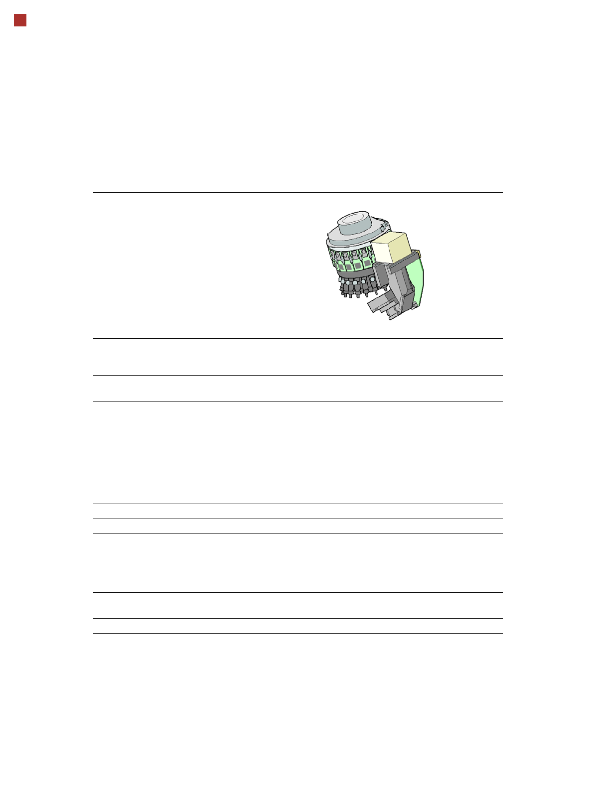
SIPLACE MultiStar (CPP M)
SIPLACE MultiStar (CPP M)
With component camera type 45
Component range
a
a) Please note that the placeable component range is also affected by the pad geometry, the customer-
specific standards, the component packaging tolerances and the component tolerances.
01005 to 15 mm x 15 mm
Component spec.
Max height
b
Max. height
c
Min. lead pitch
Min. lead width
Min. ball pitch
Min. ball diameter
Min. dimensions
Max. dimensions
Max. weight
b) CPP M head: in low installation position
c) CPP M head: in high installation position
6.0 mm
8.5 mm
250 µm / 120 µm
d
50 µm
140 µm
70 µm
0.11 mm x 0.11 mm
15 mm x 15 mm
4 g
d) Only available for components which are within the camera range of focus: ± 1.3 mm.
Set-down force 1.0 - 15 N
Nozzle types 20xx, 28xx
X/Y accuracy
e
With "accuracy class"
f
Without "accuracy class"
e) The benchmark and accuracy values are measured during the machine acceptance tests and corre-
spond to the conditions set out in the ASM scope of service and supply.
f) Setting in SIPLACE Pro Component Shape Editor
± 20 µm/3σ
± 25 µm/3σ
Angular accuracy ± 0.18° / 3σ
Illumination levels 5
10
Placement heads
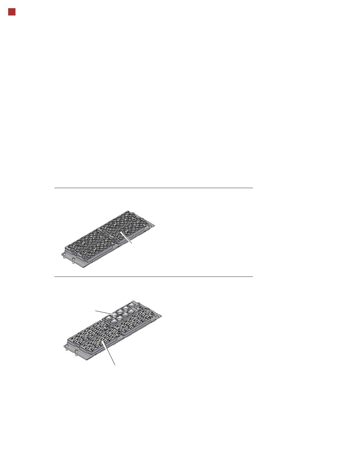
Nozzle changer
Nozzle changer for the SIPLACE SpeedStar (C&P20 M2)
Nozzle changer for the SIPLACE MultiStar (CPP M)
Magazine for 20 nozzles of type 40xx
Magazine for 9 nozzles of
type 28xx
Magazine for 20 nozzles of type 20xx
Description
Nozzle changers increase the flexibility of the placement heads when it comes to processing
different components. The nozzle configuration can be rapidly adjusted to changing place-
ment jobs. Precisely defined positions and perfect nozzle seat in the garage ensure minimum
radial eccentricity on the placement head.
The nozzle changers feature a monitoring circuit.This checks whether the nozzle magazines
are seated correctly on the mount.In addition, the nozzle changer recognizes whether the
magazines are for 40xx, 20xx or 28xx nozzles by the code.