00191174-01.pdf - 第7页
User’s Manual Test Program S ITEST 0 Introduction Software Version 10.xx Edition 03/98 0.2 Flow chart for t he calibration procedure 0 - 3 Information on the flow chart " calibration procedure Siplace 80F calibratio…
0 Introduction User’s Manual Test Program SITEST
0.2 Flow chart for the calibration procedure Software Version 10.xx Edition 03/98
0 - 2
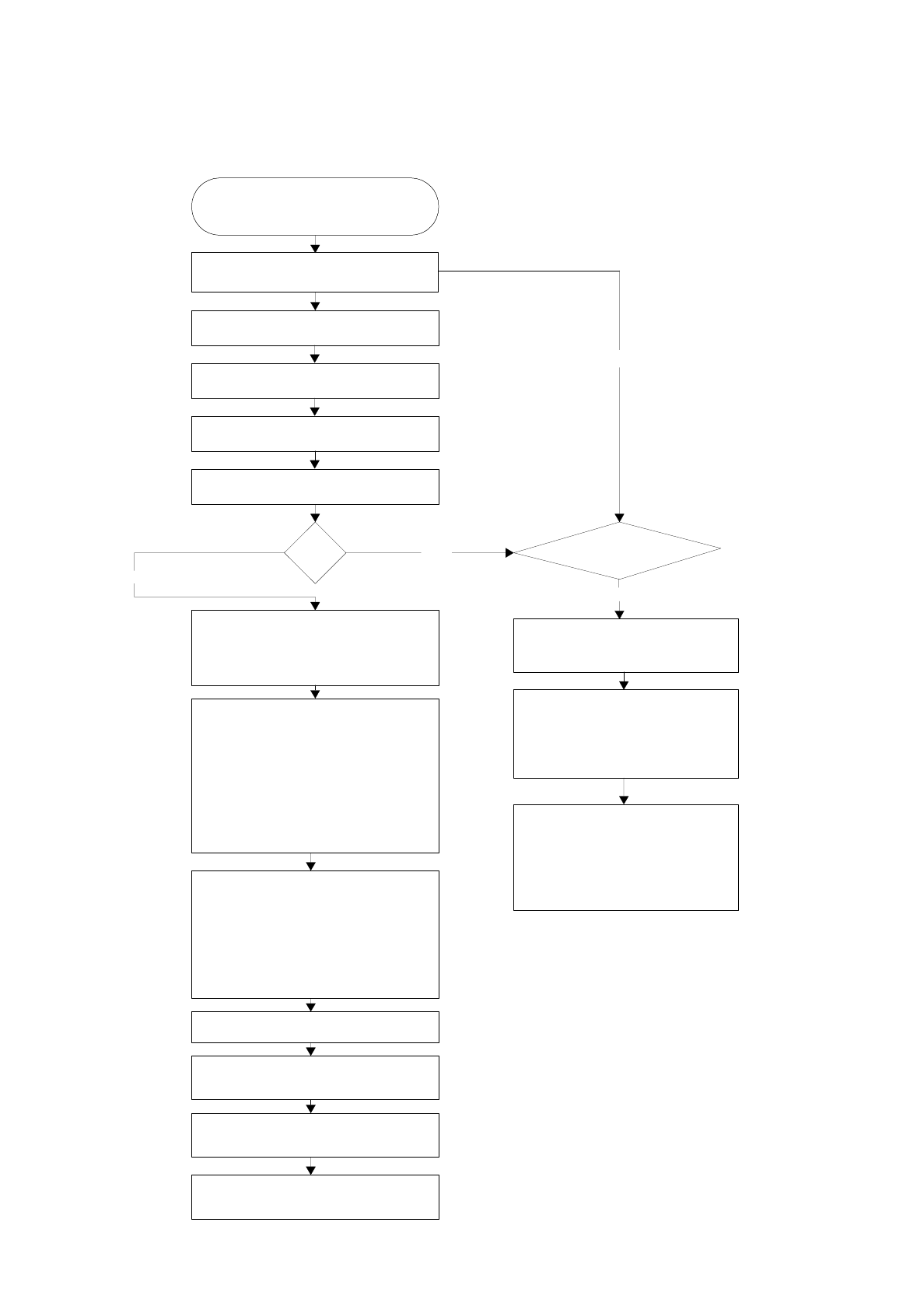
0.2 Flow chart for the calibration procedure
Start calibration
2. calibrate pcb camera
3. calibrate component camera
4. measure segment offset
5. offset pcb/component camera
6. calibrate machine zero point
(check travel range of the main
axes after a mechanical change)
7. IC camera
(menu meas. focus of camera)
a) adjust focus
b) measure z- delta
c) calibrate IC camera
d) offset pcb/IC-camera
8. FC camera
(menu meas. focus of camera)
a) adjust focus
b) measure z- delta
c) calibrate FC camera
9. calibrate coplanmodul
10. feeder table
calibrate track 1 a. 120
11. calibrate nozzle changer
revolver head
12. calibrate nozzle changer
IC head
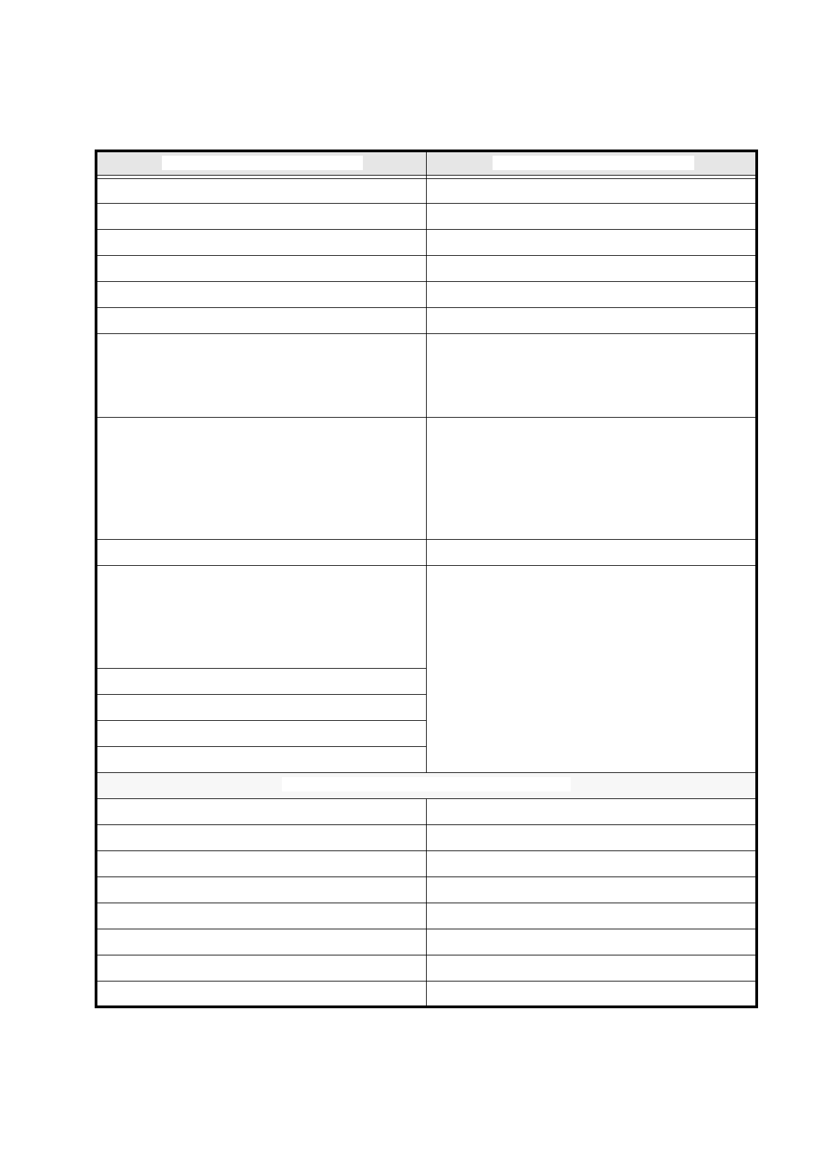
80S
6. calibrate machine zero
points (both gantries)
calibrate
2. gantry
yes
yes
no
7. feeder table with gantry1
and gantry 2
calibrate track 1 a. 120
8. nozzle changer revolver-
head
(calibrate both gantries z, x
and y)
no
1. move to calibration piece
User’s Manual Test Program SITEST 0 Introduction
Software Version 10.xx Edition 03/98 0.2 Flow chart for the calibration procedure
0 - 3
Information on the flow chart "calibration procedure
Siplace 80F calibration procedure Siplace 80S calibration procedure
1. Move to calibration piece 1. Move to calibration piece
2. Calibrate pcb camera 2 .Calibrate pcb- camera
3. Calibrate component camera 3. Calibrate component camera
4. Measure segment offset (12x617 Nozzles) 4. Measure segment offset (12x617 Nozzles)
5. Offset pcb/component camera 5. Offset pcb/component camera
Save data Save data
6. calibrate machine zero point 6. Change gantry (select gantry
gantry 1 activ -> gantry 2 activ) repeat step
1 - 6, but do not move the machine calibration
gauge until you are ready.
7. Calibrate IC camera with nozz. 416
(menu meas. focus of camera)
a) Adjust focus
b) measure z- delta with calibration piece
c) Calibrate IC camera
d) Offset pcb/IC camera
7.a) Calibrate feeder table with portal 1
b) Calibrate feeder table with portal 2
Save data Save data
8. Calibrate FC camera with nozz. 416
(menu meas. focus of camera)
a) Adjust focus
b) measure z- delta with calibr. piece
c) Calibrate FC camera
8. Calibrate nozzle changer RV head
9. Calibrate coplanmodul
10. Feeder table (Calibrate track 1 und 120)
11. Calibrate nozzle changer RV- head
12. Calibrate nozzle changer IC- head
Perform the following measurements, if required:
13. Measure travel ranges X/Y 9. Measure travel ranges X/Y
14. Calibrate the pos. of the pcb reference corner 10. Calibrate the pos. of the pcb reference corner
15. Calibrate width adjustment (with 100 mm PCB) 11. Calibrate width adjustment (with 100 mm PCB)
Save data Save data
16. PCB mapping 12. PCB mapping (both gantries)
17. IC mapping 13. RV- Mapping (both gantries)
18. RV-Mapping
Save data Save data
Tab. 0.2 - 1 Flow chart "calibration prodedure"
0 Introduction User’s Manual Test Program SITEST
0.3 Program Options Software Version 10.xx Edition 03/98
0 - 4
0.3 Program Options
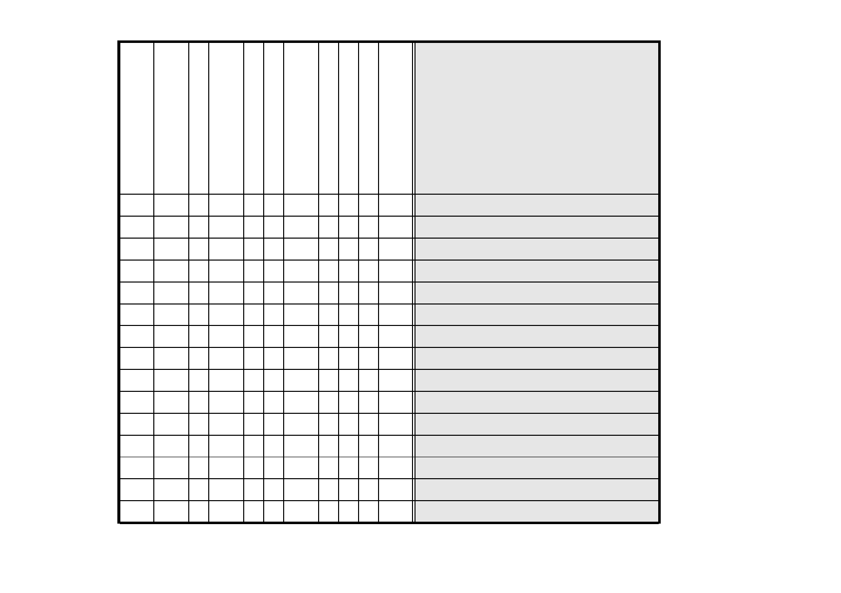
The chart below provides a rough overview of the commissioning and servicing activities that can be perfor-
med using the menu options of the test program.
Commissioning /
Servicing Activity
Axis functions (chap. 3)
Functions of the Motor Control Board (chap.4)
Calibration of the Comp. Camera (chap. 4)
Calibration of the PCB-C amera (chap.4)
Measuring the Segment Offset I (chap.4)
Offset of the PCB Camera to Comp.camera (chap.4)
Measuring the Centering Offset (chap.4))
Calibrating of the Machine Zero Point (chap.4)
ICalibration of the IC-Camera
Offset IC-Camera to Comp.camera (chap.4)
Calibration of the Flip-Chip-Camera (chap.4)
Calibration of the Copl.Laser Module (chap.4)
Calibration of the Nozzle Changer (chap.4)
Mapping (chap.. 5)
Measuring the Pick-Up Positions of Tracks 1 and 120
Initial start-up XXXXXXXXXXXXXXX
Electrical adjustment X X
Head replacement XXXXXXXXXXXXXXX
PCB camera replacement X X
Component camera replace-
ment
XXXX X
IC-camera replacement X X
Flip-Chip-camera replacement X
Installation/Replacement
Coplanarity laser module
X
Nozzle changer replacement X
Incremental encoder replace-
ment
XXX
Replacement of support of
component table
X
Tab. 0.3 - 1 Inbetriebnahme-/Servicearbeiten