00193826-01.pdf - 第10页
Index of Figures User Manual S IPLACE CS 06/2003 US Edition 10 Fig. 3.11 - 5 Nozzle c hanger - p osition dete ction . . . . . . . . . . . . . . . . . . . . . . . . . . . . . . . . . . . . . . . . . . 97 Fig. 3.12 - 1 PCB…
User Manual SIPLACE CS Index of Figures
06/2003 US Edition
9
Index of Figures
Page
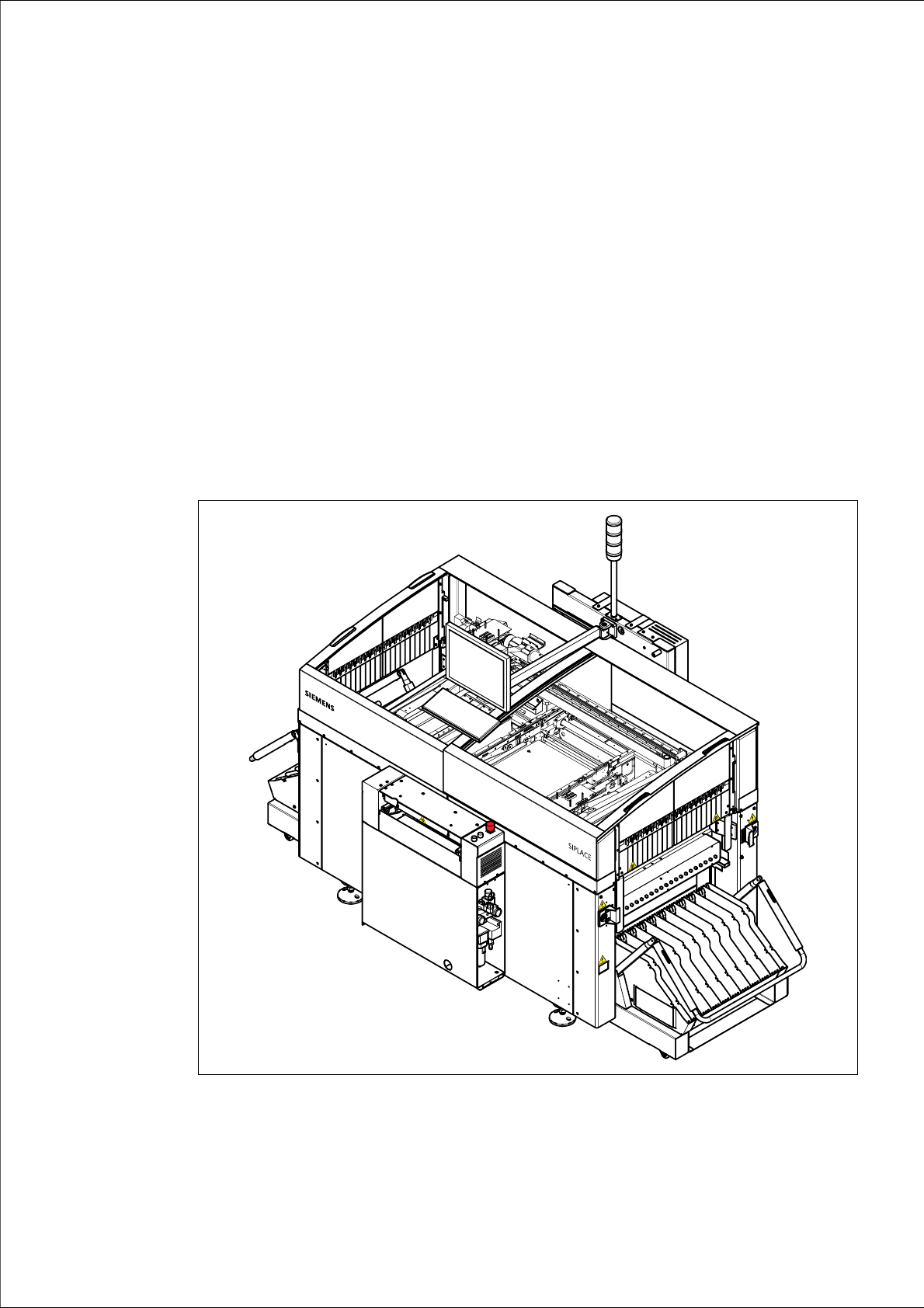
Fig. 1.0 - 1 SIPLACE CS placement system . . . . . . . . . . . . . . . . . . . . . . . . . . . . . . . . . . . . . . . . . . . . 11
Fig. 1.1 - 1 The SIPLACE home page . . . . . . . . . . . . . . . . . . . . . . . . . . . . . . . . . . . . . . . . . . . . . . . . . 12
Fig. 2.2 - 1 Warning labels on the machine - part 1 . . . . . . . . . . . . . . . . . . . . . . . . . . . . . . . . . . . . . . . 22
Fig. 2.2 - 2 Warning labels on the machine - part 2 . . . . . . . . . . . . . . . . . . . . . . . . . . . . . . . . . . . . . . . 23
Fig. 2.2 - 3 Warning labels on the machine - part 3 . . . . . . . . . . . . . . . . . . . . . . . . . . . . . . . . . . . . . . . 24
Fig. 2.2 - 4 Warning labels on the machine - part 4 . . . . . . . . . . . . . . . . . . . . . . . . . . . . . . . . . . . . . . . 25
Fig. 2.2 - 5 Warning label W205 on the top of the tape cutter . . . . . . . . . . . . . . . . . . . . . . . . . . . . . . . 28
Fig. 2.2 - 6 Warning label W205 on the used tape channel and on the used tape chute. . . . . . . . . . . 29
Fig. 2.2 - 7 Warning label W207 on the servo unit Macrolon panel . . . . . . . . . . . . . . . . . . . . . . . . . . . 30
Fig. 2.2 - 8 Warning label W207 on the PCB conveyor control unit . . . . . . . . . . . . . . . . . . . . . . . . . . . 31
Fig. 2.2 - 9 Warning label W211 on the CEKON plug. . . . . . . . . . . . . . . . . . . . . . . . . . . . . . . . . . . . . . 32
Fig. 2.2 - 10 Warning label W110 on the EMERGENCY STOP buttons . . . . . . . . . . . . . . . . . . . . . . . . 33
Fig. 2.2 - 11 Warning label Danger of crushing on the component trolley . . . . . . . . . . . . . . . . . . . . . . . 34
Fig. 2.4 - 1 Safety instructions on the component trolley . . . . . . . . . . . . . . . . . . . . . . . . . . . . . . . . . . . 36
Fig. 2.4 - 2 Protective covers on the SIPLACE automatic placement machine . . . . . . . . . . . . . . . . . . 38
Fig. 2.4 - 3 Securing the placement machine to prevent it slipping . . . . . . . . . . . . . . . . . . . . . . . . . . . 39
Fig. 2.5 - 1 Safety equipment in the placement machine . . . . . . . . . . . . . . . . . . . . . . . . . . . . . . . . . . . 42
Fig. 2.5 - 2 Stop and EMERGENCY STOP buttons . . . . . . . . . . . . . . . . . . . . . . . . . . . . . . . . . . . . . . . 43
Fig. 2.5 - 3 Guard on the placement machine . . . . . . . . . . . . . . . . . . . . . . . . . . . . . . . . . . . . . . . . . . . 44
Fig. 2.5 - 4 Location of the buttons and protective contactor combinations K1, K2 . . . . . . . . . . . . . . . 45
Fig. 2.5 - 5 Safety circuits. . . . . . . . . . . . . . . . . . . . . . . . . . . . . . . . . . . . . . . . . . . . . . . . . . . . . . . . . . . 49
Fig. 2.5 - 6 Guard . . . . . . . . . . . . . . . . . . . . . . . . . . . . . . . . . . . . . . . . . . . . . . . . . . . . . . . . . . . . . . . . . 50
Fig. 2.6 - 1 Test sockets on the voltmeter unit in the servo unit . . . . . . . . . . . . . . . . . . . . . . . . . . . . . . 51
Fig. 2.7 - 1 Compressed air unit on the placement system . . . . . . . . . . . . . . . . . . . . . . . . . . . . . . . . . 53
Fig. 2.8 - 1 Position of the control unit, servo unit, main switch, service socket and
compr. air unit in the placement system. . . . . . . . . . . . . . . . . . . . . . . . . . . . . . . . . . . . . . . 55
Fig. 3.1 - 1 Overall view of the placement system . . . . . . . . . . . . . . . . . . . . . . . . . . . . . . . . . . . . . . . . 63
Fig. 3.3 - 1 Electrical and pneumatic connection points on the placement system part 1 . . . . . . . . . . 67
Fig. 3.3 - 2 Electrical and pneumatic connection points on the placement system part 2 . . . . . . . . . . 68
Fig. 3.5 - 1 Dimensions of the placement system in millimeters. . . . . . . . . . . . . . . . . . . . . . . . . . . . . . 70
Fig. 3.5 - 2 The placement system’s center of gravity . . . . . . . . . . . . . . . . . . . . . . . . . . . . . . . . . . . . . 71
Fig. 3.5 - 3 Dimensions of the placement system with component trolley in millimeters . . . . . . . . . . . 72
Fig. 3.5 - 4 Wiring radius of the component trolley in millimeters. . . . . . . . . . . . . . . . . . . . . . . . . . . . . 73
Fig. 3.6 - 1 Overview of the modules - controls - part 1 . . . . . . . . . . . . . . . . . . . . . . . . . . . . . . . . . . . . 74
Fig. 3.6 - 2 Overview of the modules - controls - part 2 . . . . . . . . . . . . . . . . . . . . . . . . . . . . . . . . . . . . 75
Fig. 3.7 - 1 Component barcode reader . . . . . . . . . . . . . . . . . . . . . . . . . . . . . . . . . . . . . . . . . . . . . . . . 79
Fig. 3.8 - 1 Position of the gantries. . . . . . . . . . . . . . . . . . . . . . . . . . . . . . . . . . . . . . . . . . . . . . . . . . . . 81
Fig. 3.8 - 2 Structure of the X-axis . . . . . . . . . . . . . . . . . . . . . . . . . . . . . . . . . . . . . . . . . . . . . . . . . . . . 82
Fig. 3.9 - 1 Structure of the 6-segment Collect&Place head with standard component
vision camera - part 1. . . . . . . . . . . . . . . . . . . . . . . . . . . . . . . . . . . . . . . . . . . . . . . . . . . . . 84
Fig. 3.9 - 2 Structure of the 6-segment Collect&Place head with standard component
vision camera - part 2. . . . . . . . . . . . . . . . . . . . . . . . . . . . . . . . . . . . . . . . . . . . . . . . . . . . . 85
Fig. 3.10 - 1 Component vision camera on the 6-segment Collect&Place head . . . . . . . . . . . . . . . . . . 88
Fig. 3.10 - 2 PCB vision camera (standard camera). . . . . . . . . . . . . . . . . . . . . . . . . . . . . . . . . . . . . . . . 89
Fig. 3.11 - 1 Nozzle changer for the 6-segment Collect&Place head, overview. . . . . . . . . . . . . . . . . . . 91
Fig. 3.11 - 2 Magazine and nozzle holders. . . . . . . . . . . . . . . . . . . . . . . . . . . . . . . . . . . . . . . . . . . . . . . 93
Fig. 3.11 - 3 Emptying the reject bin, 6-segment Collect&Place head . . . . . . . . . . . . . . . . . . . . . . . . . . 95
Fig. 3.11 - 4 Changing the magazine . . . . . . . . . . . . . . . . . . . . . . . . . . . . . . . . . . . . . . . . . . . . . . . . . . . 96
Index of Figures User Manual SIPLACE CS
06/2003 US Edition
10
Fig. 3.11 - 5 Nozzle changer - position detection . . . . . . . . . . . . . . . . . . . . . . . . . . . . . . . . . . . . . . . . . . 97
Fig. 3.12 - 1 PCB conveyor. . . . . . . . . . . . . . . . . . . . . . . . . . . . . . . . . . . . . . . . . . . . . . . . . . . . . . . . . . . 98
Fig. 4.1 - 1 Dimensions of the placement system during transportation and setting up
in millimeters. . . . . . . . . . . . . . . . . . . . . . . . . . . . . . . . . . . . . . . . . . . . . . . . . . . . . . . . . . . 101
Fig. 4.3 - 1 Adjusting the component trolley to another PCB transport height . . . . . . . . . . . . . . . . . . 106
Fig. 5.4 - 1 Placing the tape in the springs of the S feeder. . . . . . . . . . . . . . . . . . . . . . . . . . . . . . . . . 113
Fig. 5.4 - 2 Inserting dividing plates in the component trolley tape container. . . . . . . . . . . . . . . . . . . 115
Fig. 5.4 - 3 Inserting spindles for large reels. . . . . . . . . . . . . . . . . . . . . . . . . . . . . . . . . . . . . . . . . . . . 116
Fig. 5.7 - 1 Pick-up position for components > 3 mm and </=3 mm . . . . . . . . . . . . . . . . . . . . . . . . . . 119
Fig. 5.7 - 2 Position of the component and its pick-up angle . . . . . . . . . . . . . . . . . . . . . . . . . . . . . . . 120
Fig. 5.9 - 1 Safety instructions on the component trolley . . . . . . . . . . . . . . . . . . . . . . . . . . . . . . . . . . 122
Fig. 5.9 - 2 Docking or undocking the component trolley . . . . . . . . . . . . . . . . . . . . . . . . . . . . . . . . . . 124
Fig. 5.10 - 1 Operating status indicator lamp . . . . . . . . . . . . . . . . . . . . . . . . . . . . . . . . . . . . . . . . . . . . 127
Fig. 6.2 - 1 8 mm S II feeder. . . . . . . . . . . . . . . . . . . . . . . . . . . . . . . . . . . . . . . . . . . . . . . . . . . . . . . . 132
Fig. 6.2 - 2 3 x 8 mm S feeder . . . . . . . . . . . . . . . . . . . . . . . . . . . . . . . . . . . . . . . . . . . . . . . . . . . . . . 133
Fig. 6.2 - 3 3 x 8 mm S feeder for 0201/0402 components. . . . . . . . . . . . . . . . . . . . . . . . . . . . . . . . . 134
Fig. 6.2 - 4 12/16 mm S feeder. . . . . . . . . . . . . . . . . . . . . . . . . . . . . . . . . . . . . . . . . . . . . . . . . . . . . . 135
Fig. 6.2 - 5 12 mm S feeder for capacitors based on powdered metal, model C/D . . . . . . . . . . . . . . 136
Fig. 6.2 - 6 12 mm S feeder for capacitors based on powdered metal, model E . . . . . . . . . . . . . . . . 137
Fig. 6.2 - 7 24/32 mm S feeder. . . . . . . . . . . . . . . . . . . . . . . . . . . . . . . . . . . . . . . . . . . . . . . . . . . . . . 138
Fig. 6.2 - 8 Linear vibratory feeder, type 3 . . . . . . . . . . . . . . . . . . . . . . . . . . . . . . . . . . . . . . . . . . . . . 139
Fig. 6.2 - 9 Bulk case feeder. . . . . . . . . . . . . . . . . . . . . . . . . . . . . . . . . . . . . . . . . . . . . . . . . . . . . . . . 140
Fig. 6.3 - 1 Inserting 30 or 45 mm wide feeders on the component table. . . . . . . . . . . . . . . . . . . . . . 142
Fig. 6.4 - 1 Component trolley. . . . . . . . . . . . . . . . . . . . . . . . . . . . . . . . . . . . . . . . . . . . . . . . . . . . . . . 143
Fig. 6.4 - 2 Component trolley with tape container . . . . . . . . . . . . . . . . . . . . . . . . . . . . . . . . . . . . . . . 144
Fig. 6.4 - 3 Compressed air supply for bulk case feeders. . . . . . . . . . . . . . . . . . . . . . . . . . . . . . . . . . 145
Fig. 6.4 - 4 Connecting the compressed air supply for bulk case feeders . . . . . . . . . . . . . . . . . . . . . 146
Fig. 6.4 - 5 Support for the middle tape reel for 3x 8 mm feeders . . . . . . . . . . . . . . . . . . . . . . . . . . . 147
Fig. 6.5 - 1 Used tape cutter . . . . . . . . . . . . . . . . . . . . . . . . . . . . . . . . . . . . . . . . . . . . . . . . . . . . . . . . 148
Fig. 6.5 - 2 Inserting the tape into the tape cutter. . . . . . . . . . . . . . . . . . . . . . . . . . . . . . . . . . . . . . . . 149
Fig. 6.5 - 3 Pull-out waste tape container in the component trolley . . . . . . . . . . . . . . . . . . . . . . . . . . 150
User Manual SIPLACE CS 1 Introduction
Software version SR.101.xx 06/2003 US Edition
11
1 Introduction
These operating instructions provide a manual or reference work for
– operating and
– setting up
the placement system. 1
The header of each chapter contains the
– release and
– software version
to which this manual applies. 1
1
Fig. 1.0 - 1 SIPLACE CS placement system