00193826-01.pdf - 第105页
User Manual SIPLAC E CS 4 Setting up the placement system Software vers ion SR.101.xx 06/ 2003 US Edition 4.2 Setting up the plac ement system 105 4.2.2 Setting up the placem ent machine Æ Raise the placeme nt system us …
4 Setting up the placement system User Manual SIPLACE CS
4.2 Setting up the placement system Software version SR.101.xx06/2003 US Edition
104
4.1.5 Power supply
4.1.5.1 Electrical ratings
4
4
4
4.1.5.2 Checking the main power supply
Check that the main power supply conforms to the prescribed machine specifications.
PLEASE NOTE:
The document entitled "Network configuration (electrical and compressed air) for SMD systems
on the customer's premises", part no. 00191409-xx, describes the action that can be taken to
meet the required specifications.
4.2 Setting up the placement system
4.2.1 Safety instructions
WARNING
– The applicable accident prevention regulations concerning the transportation of heavy goods
must be followed.
– There is a risk that the machine will tip over if you do not use the pallet jack specified in section
4.1.3
to transport the placement machine.
– In particular, you should wear safety boots to minimize the risk of crushing your feet.
– Attach the pallet jack only at the points identified by A in Fig. 4.1 - 1).
Supply voltage 3 x 200 VAC ± 5 %; 50/60 Hz (Japan)
3 x 208 VAC ± 5 %; 50/60 Hz (U.S.A)
3 x 400 VAC ± 5 %; 50/60 Hz (Europe)
Fuses 3 x 16 A (3 x 204 VAC)
Total connected load 5 kVA
Total power 2 kW
Power failure Max. 20 msec

User Manual SIPLACE CS 4 Setting up the placement system
Software version SR.101.xx 06/2003 US Edition 4.2 Setting up the placement system
105
4.2.2 Setting up the placement machine
Æ Raise the placement system using the fork-lift truck and adjust the feet until there is a gap of
830 mm between the top edge of the PCB conveyors and the bottom edge of the feet.
Æ Leave a gap of 1 to 3 mm between the PCB conveyors of the placement system.
Æ Align all the placement systems exactly in line with one another. Use a cord pulled tight to en-
sure this.
Æ Adjust each placement system using a spirit level with an accuracy of 0.02 mm/m.
Æ Lock the feet in position.
Æ Check the placement system again using the spirit level and correct the settings, if necessary.
CAUTION
Make sure that you remove all the shipping braces from the placement system. 4
Æ Fit any components that were dismantled for dispatch.
Æ Connect all the electrical and pneumatic lines.
RISK OF DEATH
The electrical connection work MUST be carried out only by appropriately trained and cer-
tified personnel. 4
4 Setting up the placement system User Manual SIPLACE CS
4.3 Adjusting the component trolley to another PCB transport height Software version SR.101.xx06/2003 US Edition
106
4.3 Adjusting the component trolley to another PCB
transport height
4.3.1 Tools
Allen keys, set up to 8 mm
4.3.2 Safety instructions
WARNING DANGER OF CRUSHING
Remove all the feeders from the component table bed before you adjust the table height of the
component trolley. Act with considerable care during the conversion process because the table
bed is very heavy. 4
4
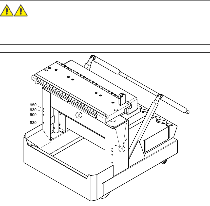
Fig. 4.3 - 1 Adjusting the component trolley to another PCB transport height
(1) Clamping screws, 4 per side
(2) Holes in the cross-beam for adjusting the table height to 830, 900, 930 and 950 mm