00193826-01.pdf - 第114页
5 Operator, Line engineer, Service engineer Us er Manual SIPLACE C S 5.4 Carrying out a walk-through inspection Software version SR.101.xx06/2003 US E dition 114 5.4.2 Check PCB support s Æ Check the magneti c PCB sup po…
User Manual SIPLACE CS 5 Operator, Line engineer, Service engineer
Software version SR.101.xx 06/2003 US Edition 5.4 Carrying out a walk-through inspection
113
5.4 Carrying out a walk-through inspection
5.4.1 Check feeder
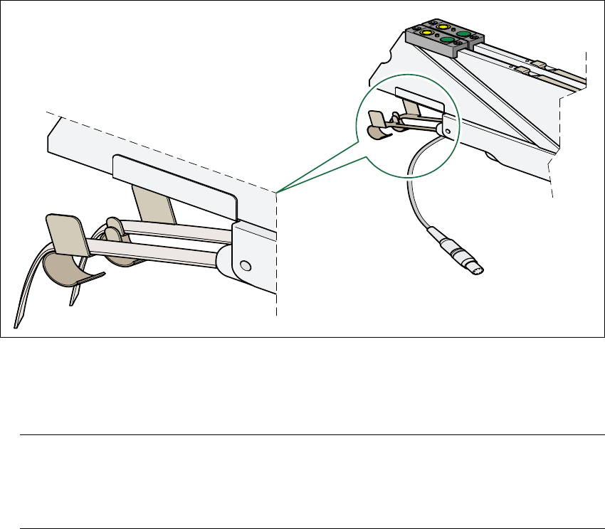
Æ Make sure that the tape is correctly placed in the springs of the S feeder.
5
Fig. 5.4 - 1 Placing the tape in the springs of the S feeder
Æ Check to see whether the tape foil removal container for the S feeder is full.
If it is full, then pull out the foil and cut it off with scissors.
NOTE
Tearing the foil instead of cutting it can lead problems with the tape removal mechanism.
For this reason the 3 x 8 mm feeders are fitted with an integral cutter. This is in the tape foil
removal container at the end of the feeder under the flaps. 5
Æ Check to ensure that the pick-up window on the feeder is the right size for the component.
Æ Check to see whether tape guides are inserted on Combi feeders (24 mm / 32 mm).
Æ Check to see whether the additional plastic guide is inserted on Combi feeders.

5 Operator, Line engineer, Service engineer User Manual SIPLACE CS
5.4 Carrying out a walk-through inspection Software version SR.101.xx06/2003 US Edition
114
5.4.2 Check PCB supports
Æ Check the magnetic PCB supports on the lifting table. They must be arranged so that they do
not collide with components on the bottom of the PCBs.
5.4.3 Splice the tape in good time
PLEASE NOTE: 5
Splice the tapes early enough so that the feeders do not become empty. Otherwise you will expe-
rience prolonged down times.
However, do not splice the tapes too early because if you wind the end of the old tape onto the
new reel after splicing, the reel holding the new tape may become overfilled and the tape will slip
off the reel and become tangled up. This will again result in pick-up errors and prolonged down
times.
User Manual SIPLACE CS 5 Operator, Line engineer, Service engineer
Software version SR.101.xx 06/2003 US Edition 5.4 Carrying out a walk-through inspection
115
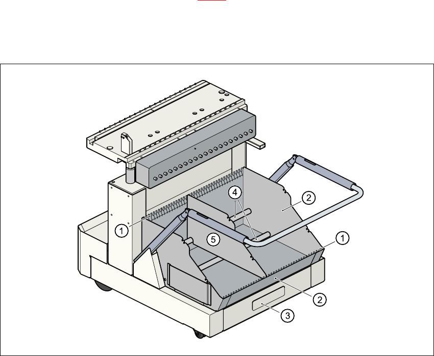
5.4.4 Inserting dividing plates in the component trolley tape container
Æ Insert the dividing plates as shown in Fig. 5.4 - 2 and remember that the smallest division of the
tape container is a 2x division. This will help avoid placement errors.
Æ Check that the dividing plates engage in the same positions on both guide rails. Otherwise the
dividing plate will be offset or bent.
5
Fig. 5.4 - 2 Inserting dividing plates in the component trolley tape container
(1) Guide rail for the dividing plates
(2) tape container
(3) Waste tape container
(4) Supporting rod for the dividing plates
(5) Dividing plate