00193826-01.pdf - 第116页
5 Operator, Line engineer, Service engineer Us er Manual SIPLACE C S 5.4 Carrying out a walk-through inspection Software version SR.101.xx06/2003 US E dition 116 5.4.5 Use spindles for large t ape reels. Æ Inser t spindl…
User Manual SIPLACE CS 5 Operator, Line engineer, Service engineer
Software version SR.101.xx 06/2003 US Edition 5.4 Carrying out a walk-through inspection
115
5.4.4 Inserting dividing plates in the component trolley tape container
Æ Insert the dividing plates as shown in Fig. 5.4 - 2 and remember that the smallest division of the
tape container is a 2x division. This will help avoid placement errors.
Æ Check that the dividing plates engage in the same positions on both guide rails. Otherwise the
dividing plate will be offset or bent.
5
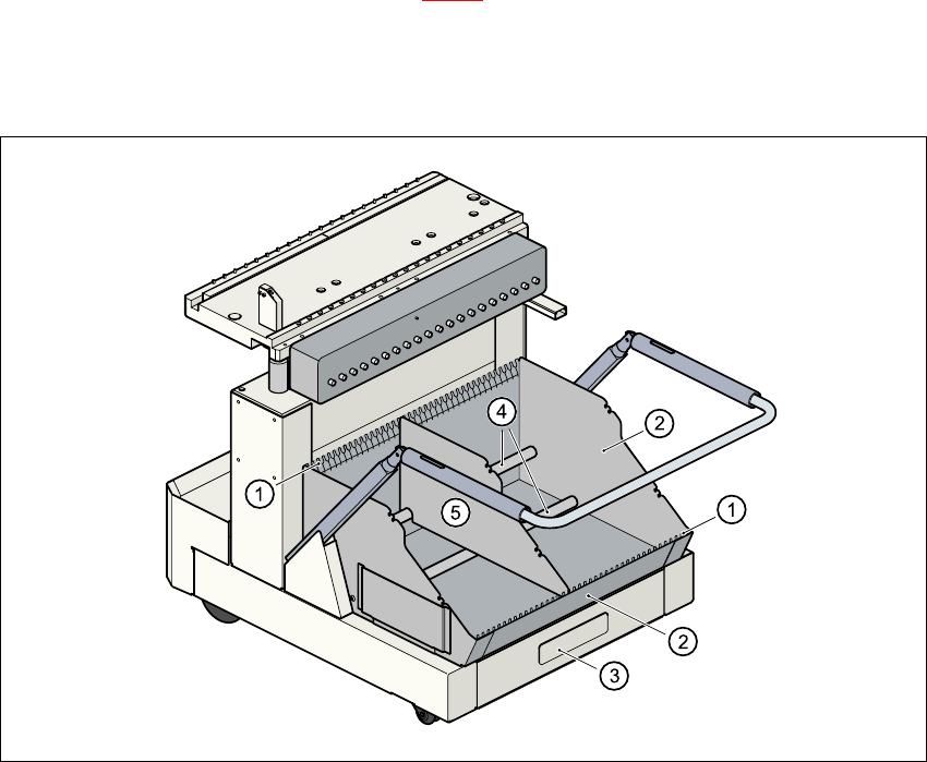
Fig. 5.4 - 2 Inserting dividing plates in the component trolley tape container
(1) Guide rail for the dividing plates
(2) tape container
(3) Waste tape container
(4) Supporting rod for the dividing plates
(5) Dividing plate
5 Operator, Line engineer, Service engineer User Manual SIPLACE CS
5.4 Carrying out a walk-through inspection Software version SR.101.xx06/2003 US Edition
116
5.4.5 Use spindles for large tape reels.
Æ Insert spindles into the dividing plates when using large tape reels.
PLEASE NOTE
We recommend that you use spindles if the tape reel diameter exceeds 7". This will ensure that
the feeders operate reliably.
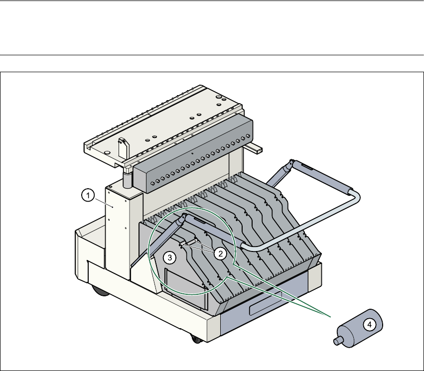
Fig. 5.4 - 3 Inserting spindles for large reels
(1) Component trolley
(2) Position of the spindles
(3) Dividing plate
(4) Spindle (enlarged)
User Manual SIPLACE CS 5 Operator, Line engineer, Service engineer
Software version SR.101.xx 06/2003 US Edition 5.5 Preliminary set-up of the placement station
117
5.5 Preliminary set-up of the placement station
Carry out the following steps to complete the preliminary set-up of the placement station.
Æ Remove the tapes from the feeders and vacuum the surfaces of the modules and the area
around the tape guide clean with the vacuum cleaner.
Æ Empty the waste tape container (see item 3 in Fig. 5.4 - 2).
Æ Clean the supporting surfaces of the feeders with a cloth moistened with alcohol.
Æ Apply a small amount of WD40 corrosion protection to the supporting surfaces with a lint-free
cloth.
Æ Use a vacuum cleaner or use a brush with short bristles to remove loose components from the
component tables.
CAUTION
Avoid removing components from the magnetic rail of the component feeder table with your
fingers. You may hurt yourself with tiny splinters of metal. 5
NOTE
The compressed air distributor rail on the component table is used to connect the bulk case
feeders. This rail runs parallel to the PCB transport and has nozzles with the openings on
the top. Make sure that the nozzles do not get dirty or come into contact with oil or grease.
Grease, oil and dirt can cause malfunctions in the feeder or may cause the components in
the feeder to become unusable! 5
Æ Check the surface of the magnetic rail for irregularities or damage and smoothen with an oil-
stone when necessary.
Æ Clean the magnetic rail with a cloth moistened with alcohol.
Æ Apply a small amount of WD40 corrosion protection to the magnetic rail with a lint-free cloth.
Æ Clean the supporting surfaces of the component tables with a cloth moistened with alcohol,
and then apply a small amount of WD40 corrosion protection with a lint-free cloth.
Æ Clean the tape container with a vacuum cleaner.
Æ Make sure that the feeders are divided up correctly.
Æ Are all the plugs of the feeder plugged in to the correct location?
Æ Make sure that the spacing in the tape transport of the feeder is correct.
Æ Shorten the used tape on the front of the feeder to a length of 1 cm.