00193826-01.pdf - 第122页
5 Operator, Line engineer, Service engineer Us er Manual SIPLACE C S 5.9 Docking the component trolley in or out Sof tware version SR. 101.xx06/2003 US Edition 122 5.9 Docking the componen t trolley in or out 5.9.1 Safet…

User Manual SIPLACE CS 5 Operator, Line engineer, Service engineer
Software version SR.101.xx 06/2003 US Edition 5.8 Refilling components
121
5.8 Refilling components
The online help contains information on refilling components with and without barcodes.
Æ With tape feeders, make sure that you always splice on a new tape early enough so that the
feeders do not run out of components.
Æ However, do not splice the tapes too early because if you wind the tape onto the new reel after
splicing the end of the old tape, the reel with the new tape may be overfilled. The tape could
then slip off the reel and become tangled. Under certain circumstances, this could cause pick-
up errors and prolonged down times.
Æ Always insert spindles when using tape reels of 7" and larger (see Fig. 5.4 - 3) and make sure
that the dividing plates are inserted correctly (see Fig. 5.4 - 3
).
5 Operator, Line engineer, Service engineer User Manual SIPLACE CS
5.9 Docking the component trolley in or out Software version SR.101.xx06/2003 US Edition
122
5.9 Docking the component trolley in or out
5.9.1 Safety instructions on docking and undocking the component trolley
5
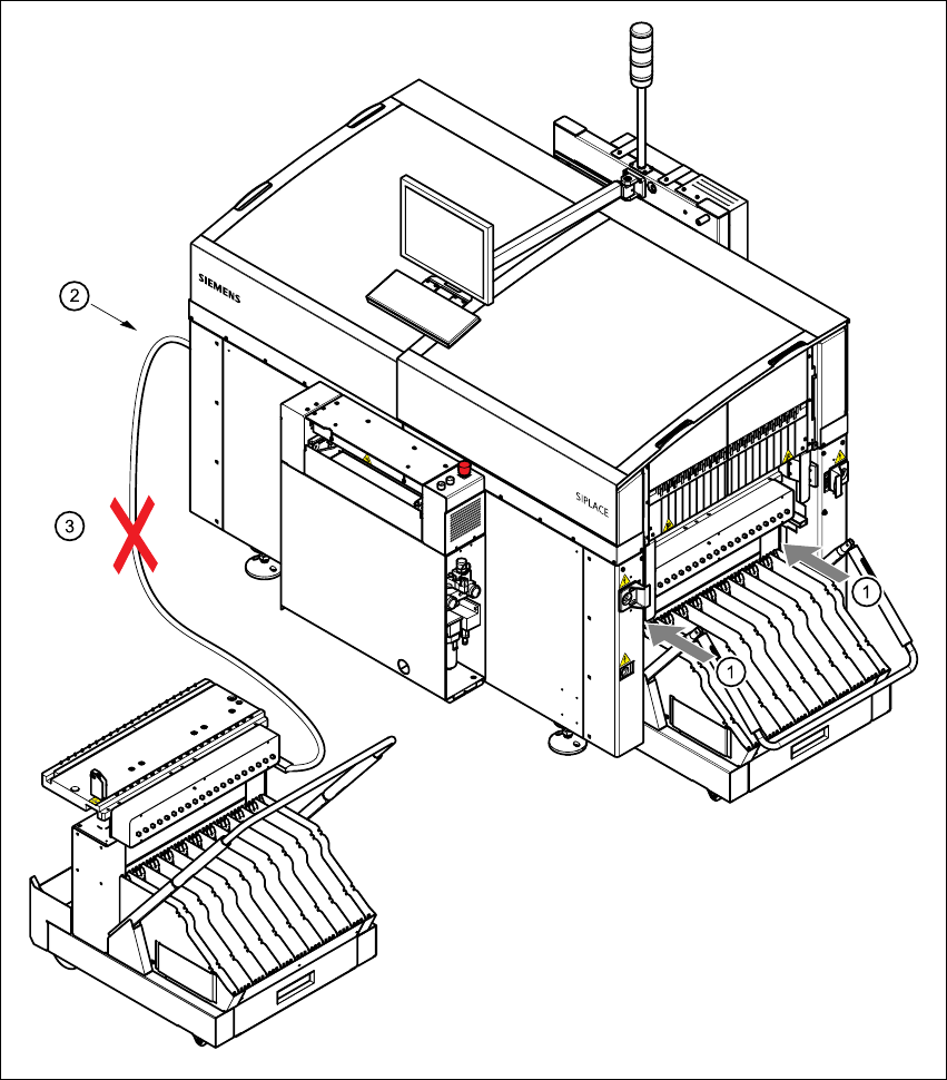
Fig. 5.9 - 1 Safety instructions on the component trolley

User Manual SIPLACE CS 5 Operator, Line engineer, Service engineer
Software version SR.101.xx 06/2003 US Edition 5.9 Docking the component trolley in or out
123
WARNING 5
Æ Never reach into the gap between the component trolley and the placement system frame
(item 1 in Fig. 5.9 - 1
).
Æ Always check that the component trolley is docked on the placement system before connecting
or disconnecting the power cable for the component trolley at the socket on the placement sys-
tem (item 25.9 - 1
).
Æ NEVER connect the connecting cable for the component trolley to the socket on the placement
system and then operate the component trolley outside the machine via the compressed air
control unit (item 3 in Fig. 5.9 - 1).