00193826-01.pdf - 第128页
5 Operator, Line engineer, Service engineer Us er Manual SIPLACE C S 5.10 Operating status indicator lamp Software version SR.101.xx06/2003 US Edition 128
User Manual SIPLACE CS 5 Operator, Line engineer, Service engineer
Software version SR.101.xx 06/2003 US Edition 5.10 Operating status indicator lamp
127
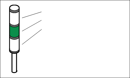
5.10 Operating status indicator lamp
The sequence of colors of the indicator lamp is white (L1) - green (L2) - white (L3). These lamps
are used to signal operating statuses and malfunctions of the placement system.
5.10.1 Description of the functions
Fig. 5.10 - 1 Operating status indicator lamp
5.10.2 General operating statuses
– Operating status lamp (green) on continuously
The placement system is in service.
– Operating status lamp (green) flashes
The placement system is waiting for a PCB on the input belt or the placement system is waiting
until the output belt is free.
– Top white fault indicator lamp L1 flashes
One or more tracks are empty on the right-hand side of the placement system. The placement
system continues to place any remaining components.
– Bottom white fault indicator lamp L3 flashes
One or more tracks are empty on the left-hand side of the placement system. The placement
system continues to place any remaining components.
– Top white fault indicator lamp (L1) on continuously - green operating status lamp (L2) off
An error has occurred on the right-hand side of the placement system -> the placement system
has stopped.
– Bottom white fault indicator lamp (L3) on continuously - green operating status lamp (L2) off
An error has occurred on the left-hand side of the placement system -> the placement system
has stopped.
– Both white fault indicator lamps (L1 and L3) on continuously - green operating status lamp off
An error has occurred that affects the entire placement system -> the placement system has
stopped.
5
L1: Fault indicator lamp (white)
L2: Fault indicator lamp (green)
L3: Fault indicator lamp (white)
5 Operator, Line engineer, Service engineer User Manual SIPLACE CS
5.10 Operating status indicator lamp Software version SR.101.xx06/2003 US Edition
128

User Manual SIPLACE CS 6 Component handling
Software version SR.101.xx 06/2003 US Edition 6.1 General
129
6 Component handling
6.1 General
6.1.1 Feeders
The following feeders are currently available for supplying various component types to the place-
ment system:
Tape Feeders 6
– 8 mm S II feeder
– 3 x 8 mm S feeder, 3 x 8 mm S feeder for 0201/0402 components
– 12 mm S feeder for capacitors based on powdered metal, model C/D
– 12 mm S feeder for capacitors based on powdered metal, model E
– S feeder for 12/16 mm and 24/32 mm components
Other feeders 6
– Vibratory stick feeder, type 3
– bulk case feeder
These feeders can be used to process the latest package forms of all components, such as bulk
cases, stick magazines, and taped components.
The most important feature of the modular component feeding system is its great flexibility. For
example, the feeding intervals can be set on the feeder. The tape feeders can handle both paper
and blister tapes. In this way, just a small selection of feeders is sufficient for inserting a wide
range of component types.
The position detection (vision) system on the feeders enables the precise component pick-up
position to be determined. The position is determined automatically whenever the feeder or com-
ponent trolley is changed.
Feeders can thus be changed quickly and easily, even by inexperienced personnel.
PLEASE NOTE 6
Detailed information on the feeders is contained in the component feeder operating instructions.6