00193826-01.pdf - 第150页
6 Component handling User Manual SIPLACE CS 6.5 Used tape c utter Software version SR.101.xx06/2003 US Edition 150 PLEAS E NOTE On SIPLA CE aut omatic pl acement sy stems, on ly use t he tape feed ers speci fied for thes…
User Manual SIPLACE CS 6 Component handling
Software version SR.101.xx 06/2003 US Edition 6.5 Used tape cutter
149
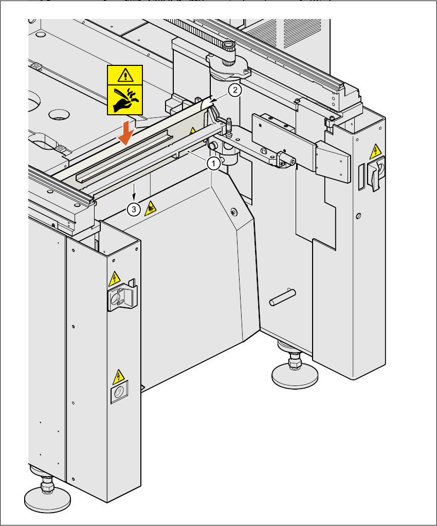
6.5.2 Inserting the tape into the tape cutter
Fig. 6.5 - 2 Inserting the tape into the tape cutter
(1) Used tape channel
(2) Used tape
(3) To used tape cutter
6 Component handling User Manual SIPLACE CS
6.5 Used tape cutter Software version SR.101.xx06/2003 US Edition
150
PLEASE NOTE
On SIPLACE automatic placement systems, only use the tape feeders specified for these ma-
chines. The used tape channel which removes the used tape is located upstream of the feeders.6
Æ Insert the tape into the feeder as described in the corresponding section.
Æ Guide the used tape into the used tape channel of the cutter as described in Fig. 6.5 - 2.
The used tape guide channels are located upstream of the feeders. They are positioned directly
above the used tape cutters.
The tape is automatically guided through the used tape guide channel into the used tape cutter
below. There, the tape is shredded by the pneumatically-actuated cutting blade. The waste tape
then passes via the waste tape chute into the waste container of the component trolley.
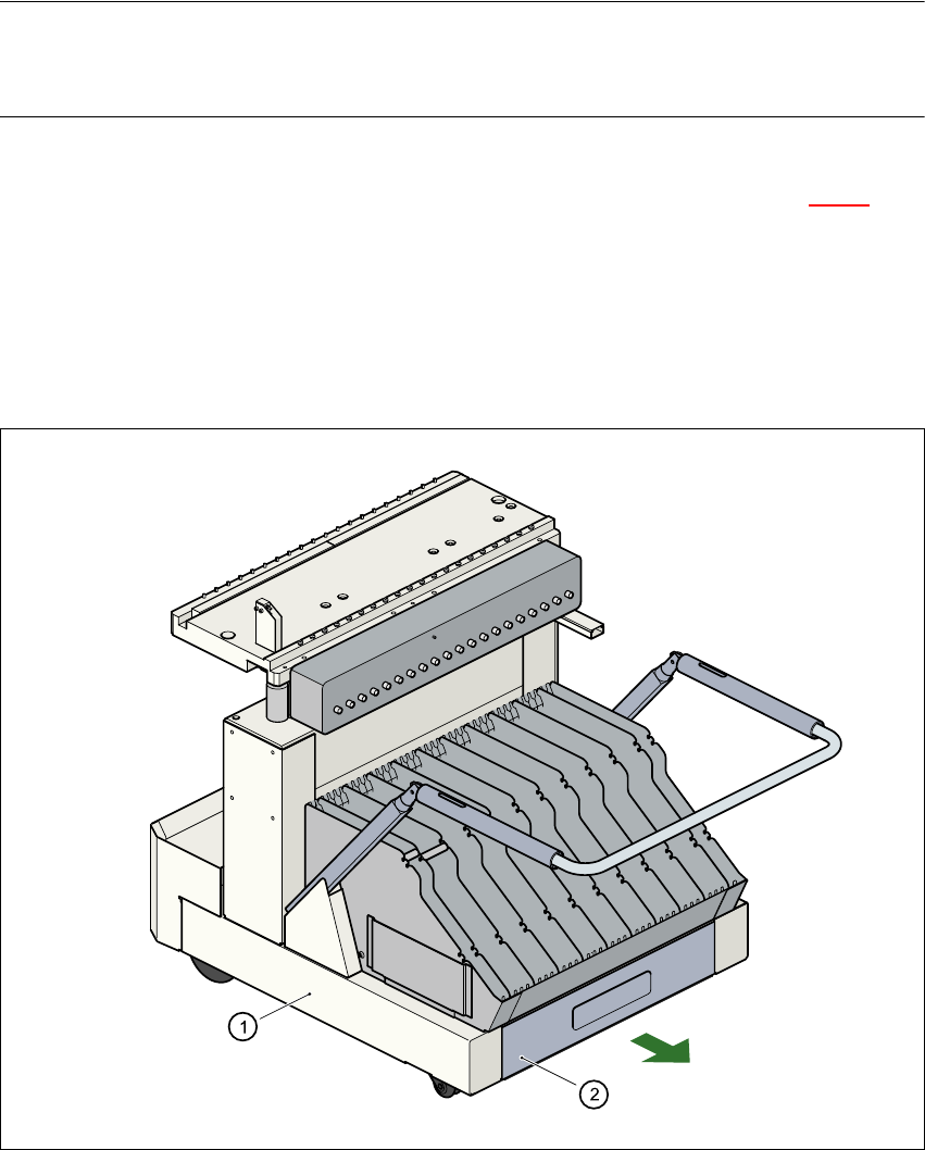
Fig. 6.5 - 3 Pull-out waste tape container in the component trolley
(1) Component trolley
(2) Waste tape container, pull-out

User Manual SIPLACE CS Index
06/2003 US Edition
151
Index
Ziffern
12 mm S feeder for capacitors based on powdered
metal, model E
model C/D
136
model E
137
12/16 mm S feeder
135
24/32 mm S feeder
138
3 x 8 mm S feeder
133
3 x 8 mm S feeder for 0201/0402 components
134
6-segment Collect&Place head
63, 65, 84
angular accuracy
65
placement accuracy
65
6-segment Collect&Place head with standard com-
ponent vision camera
angular accuracy
86
component specifications
86
component vision camera
84
description
86
forced air valve
85
max. placement rate
86
maximum stroke of the Z-axis
86
motor for "Reject" valve adjustment drive
84
nozzle types
86
placement accuracy
86
programable set-down force
86
range of components
86
star motor
84
star with 6 sleeves
84
structure
84
technical data
86
turning station
85
vacuum generator
85
Z-axis drive
84
8 mm S II feeder
132
A
abbreviations
16
ambient factors, permissible
69
atmospheric humidity
69
authorized accessories
20
avoiding track errors
119
B
bulk case feeder
140
C
carrying out a set-up check
112
carrying out a walk-through inspection
113
center of gravity coordinates
71
center of gravity of the placement system
71
changing shift
112
checking the magnetic rails
117
cleaning the supporting surfaces of the feeders
117
Collect&Place principle
86
communications connection for component trolley
67
component barcode reader
75, 77, 78, 79
connection
80
data entry
80
filter for suppressing data
80
number of barcodes
80
number of characters
80
preset code types
80
technical data
80
component barcode, general
79
component coordinate system
120
component coordinate system and pick-up angle
120
component counter
45, 75, 76
component pick-up angle
120
component supply
65
component trolley
143, 144, 150
communication unit
143
component feeder table
143
compressed air supply for bulk case feeder
144
compressed air supply for bulk case feeders
145
control button for raising the component feeder
table
143
docking in or out
122
handle for locking and lowering the component
feeder table
143
note on operational safety
143
structure
143