00193826-01.pdf - 第56页
2 Operational safety User Manual SIPLACE CS 2.8 Energy state of the machine af ter switching off at t he main switch Sof tware version SR. 101.xx06/2003 US Edition 56 2.8.1 Placement system switched of f at the main powe…
User Manual SIPLACE CS 2 Operational safety
Software version SR.101.xx 06/2003 US Edition 2.8 Energy state of the machine after switching off at the main switch
55
2.8 Energy state of the machine after switching off at
the main switch
WARNING 2
Automatic placement systems from the SIPLACE family are powered with 3 x 400 V or
3 x 208 VAC (U.S.A. version) ± 5 %, 50/60 Hz mains voltage. This means that parts of the system
carry potentially fatal voltages - even when switched off at the main switch. Death, serious injury
or considerable damage may result if these automatic placement systems are handled incorrectly.
Always follow the applicable accident prevention and DIN regulations (particularly EN 60204,
part 1). The guards over the control and servo units must ONLY be opened by appropriately qual-
ified and trained personnel. 2
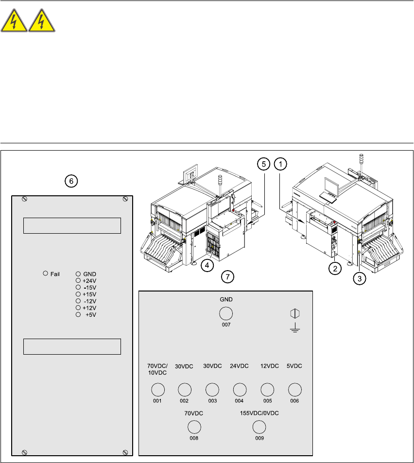
Fig. 2.8 - 1 Position of the control unit, servo unit, main switch, service socket and
compr. air unit in the placement system
(1) Main power switch Q1 (2) Compressed air unit
(3) Service socket (4) Servo unit
(5) Control unit (6) Power supply in the control unit
(7) Measuring unit, servo unit
unswitched switched

2 Operational safety User Manual SIPLACE CS
2.8 Energy state of the machine after switching off at the main switch Software version SR.101.xx06/2003 US Edition
56
2.8.1 Placement system switched off at the main power switch, but still connected
The following table specifies the voltages of assemblies when the automatic placement system is
switched off at the main switch, but still connected to the mains supply.
2
2.8.2 Placement system switched off at the main power switch and disconnected
The automatic placement system is unpowered, apart from slight residual voltages in the servo
unit.
2.8.3 Compressed air conditions in the machine after switching off at the main
power switch
When the system is switched off at the main power switch (item 1 in Fig. 2.8 - 1) or if the power
supply fails, the electrically-controlled main valve Y1 of the compressed air unit closes (Fig. 2.7 -
1, page 53 ). The pressure will drop to 0 MPa (0 bar) within 5 seconds.
Assembly Voltage
Main power filter Z1
Terminals L1, L2, L3
3 x 400 VAC (3 x 208 VAC)
Service socket
230 VAC(115 VAC)
Main switch Q1
Terminals L1, L2, L3
Terminals T1, T2,T3
3 x 400 VAC (3 x 208 VAC)
0 VAC
Servo unit (item 7 in Fig. 2.8 - 1
)
Test socket 001
Test socket 002
Test socket 003
Test socket 004
Test socket 005
Test socket 006
Test socket 008
Test socket 009
GND 007
< 12 VDC
< 12 VDC
< 12 VDC
0 VDC
0 VDC
0 VDC
< 12 VDC
< 12 VDC
Control unit (item 6 in Fig. 2.8 - 1
)
Test socket 5 V
Test socket + 12 V
Test socket – 12 V
Test socket + 15 V
Test socket – 15 V
Test socket + 24 V
GND
0 VDC
0 VDC
0 VDC
0 VDC
0 VDC
0 VDC
Tab. 2.8 - 1 Voltages of assemblies when the automatic placement system is switched off at the main switch,
but still connected to the main power

User Manual SIPLACE CS 2 Operational safety
Software version SR.101.xx 06/2003 US Edition 2.9 Lock out and tag out procedure
57
2.9 Lock out and tag out procedure
2.9.1 Purpose and scope
Before performing any maintenance work or service work, a procedure of locking and tagging
must be followed. The procedure, when followed correctly eliminates the possibility of an
employee being injured.
NOTE:
These procedures represent the minimum lock/tag out requirements for maintenance and servic-
ing work. Any additional safeguards needed to complete work safely can be specified by facilities
supervision, the safety officer, the safety committee and the health department. 2
2.9.2 Description
Whenever it becomes necessary to isolate, control and release energy, the following procedure
is to be followed
(1) Notify affected employees.
(2) Shut down the equipment. Carry out all normal stopping procedures, such as
– depressing the stop button
– shutting down the station computer and
– switching off the placement machine at the main switch.
(3) Isolate the machine from all its energy sources such as
– compressed air supply and
– power supply.
(4) Lock out the machine.
– Apply the lock and the lockout whenever possible.
– Alternative:Tagging out
If a machine can be locked out, it must be. However, there are situations where energy
isolating devices cannot accommodate locks. In these cases, the energy isolating devices
must be tagged to warn employees that the machine is de-energized for servicing. The
tag must be securely fastened, it must be placed in a position visible to all and it may only
be removed by the person who attached it.