00900002-01_UM_ASM-ProcessLens_EN.pdf - 第36页
2 Safety 2.5 Safety features 36 Instruction Guide ASM ProcessLens 02/2017 Release the EMERGENCY STOP button ► Release the EMERGENCY STOP button from latched position after being activated. ► Close the GUI messages EMS is…

2 Safety
2.5 Safety features
Instruction Guide ASM ProcessLens 02/2017 35
2.5.2.2 Description of functions
Main power switch in ON position
After switching on the main power switch, 24 V DC and 240 V AC are present.
Main power switch in OFF position
(see 2.5.2.1 "Position of switches and buttons on the machine" [}34])
The main power switch disconnects the single phase from the power supply.
DANGER
Death, serious injury or considerable damage may result if these machines are
handled incorrectly
► Always follow the applicable accident prevention and safety regulations (particularly
DIN EN 60204, part 1 or IEC 60204, part 1) and the safety regulations in your own
country.
► The safety door to the power supply must ONLY be opened by appropriately qualified
and trained personnel.
Start button, green
(see 2.5.2.1 "Position of switches and buttons on the machine" [}34])
After switching on the main power switch and having started the inspection software press the start
button to set ASM ProcessLens into regular inspection mode. Do the same if the EMERGENCY
STOP had been engaged and is now released or if the protective hood had been opened and is
now closed.
Stop button, black
(see 2.5.2.1 "Position of switches and buttons on the machine" [}34])
This button is used to stop the machine and will perform the following tasks:
●
Stop the production operations and puts the machine in idle mode.
●
The control power is still present.
EMERGENCY STOP button with forced locking
(see 2.5.2.1 "Position of switches and buttons on the machine" [}34])
The EMERGENCY STOP button is red and latches in the ON position when pressed. When you
press the EMERGENCY STOP button, the switching contact of safety interlock module opens.
The signalling contact of the EMERGENCY STOP button opens.
NOTICE
The inspection cycle is interrupted and can then either be continued or cancelled once the
machine is working correctly again.
NOTICE
ASM ProcessLens electrical diagrams
For details, please refer to the ASM ProcessLens electrical diagrams.

2 Safety
2.5 Safety features
36 Instruction Guide ASM ProcessLens 02/2017
Release the EMERGENCY STOP button
► Release the EMERGENCY STOP button from latched position after being activated.
► Close the GUI messages EMS is triggered.
► Close the GUI messages Ready to open door.
► Click on Close tab on the GUI.
ð Software will check that the hood is closed and EMS is not activated.
ð Software will lock the door and reset the safety relay.
ð Software will check that the safety relay interlock is cleared and enable the motors.
► Operator should press the START button, to resume production operation.
Key switch ON/OFF
(see 2.5.2.1 "Position of switches and buttons on the machine" [}34])
Turn on the control power manually and switch the conveyor into pass through mode when the PC
is down.
► Close the GUI program.
► Switch off the machine by the main switch.
► Wait for 30 sec and then switch on the machine at the main switch.
► Turn the key switch to the left and release to turn on the control power.
► Turn the key switch to the right.
The conveyor set to pass through running mode.
2 Safety
2.5 Safety features
Instruction Guide ASM ProcessLens 02/2017 37
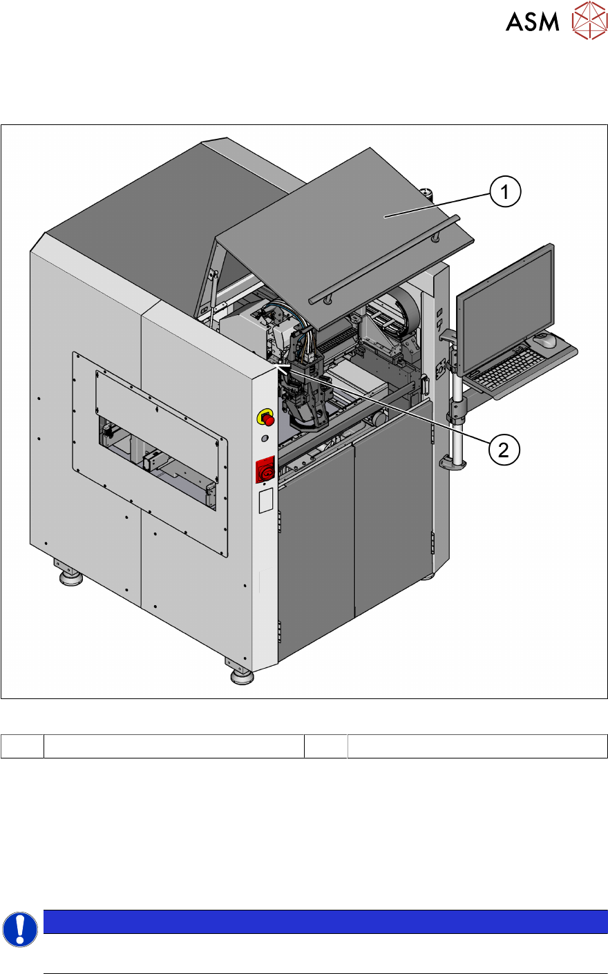
2.5.2.3 Position of protective switch on the machine
Unexpected starting of the machine is protected by the protective switch on the front protective
hood.
Fig.28: Position of protective switches on the machine
1 Front protective hood 2 Protective cover switch
Protective cover switch
(see 2.5.2.3 "Position of protective switch on the machine" [}37])
This switch check whether the protective hood is closed. When it‘s closed, the safety interlock mod-
ule is closed. The protective hood cannot be opened (it is locked) unless the user actively presses
the software button "Open front door" from the ASM SPI GUI inspection software. If the cover is
opened, the safety interlock module will open. Individual components are disabled or remain en-
abled.
NOTICE
ASM ProcessLens electrical diagrams
For details, please refer to the ASM ProcessLens electrical diagrams.