00900002-01_UM_ASM-ProcessLens_EN.pdf - 第45页
3 Machine description 3.1 Overview of the modules Instruction Guide ASM ProcessLens 02/2017 45 3 Machine description 3.1 Overview of the modules 3.1.1 Overview of assemblies Fig.29: Overview of assemblies 1 Inspection h…

2 Safety
2.8 ESD Guidelines
44 Instruction Guide ASM ProcessLens 02/2017
3 Machine description
3.1 Overview of the modules
Instruction Guide ASM ProcessLens 02/2017 45
3 Machine description
3.1 Overview of the modules
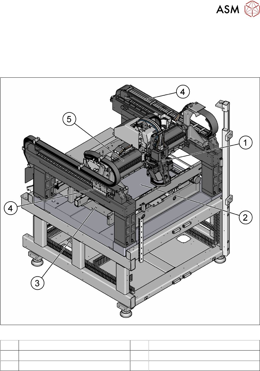
3.1.1 Overview of assemblies
Fig.29: Overview of assemblies
1 Inspection head 2 Lifting table
3 PCB conveyor assembly 4 Y-Movement for inspection head
5 X-Movement for inspection head
3 Machine description
3.1 Overview of the modules
46 Instruction Guide ASM ProcessLens 02/2017
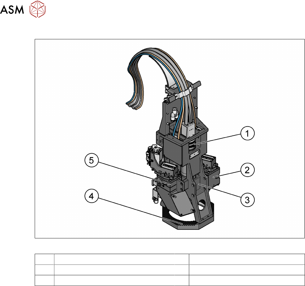
3.1.2 Inspection head
Fig.30: Inspection head
1 Imaging module (camera and lens mount) 2 Right source of 3D light
3 Top LED ring 4 Low LED ring
5 Left source of 3D light
3.1.2.1 Description
The optics head module, sitting on the gantry module, performs the image taking function, and
based on which, the expected inspection results are given.
The optics head module is split up into 2 parts, the DLP Projector Module and the Imaging Module.
The DLP projects fringes with different widths and frequencies onto the board, and the imaging
module grabs pictures and the system re-construct the 3D object based on those images taken.