00197490-03_SM_CP20-P-M2_EN保养维护.pdf - 第39页
5 DP drives 5.1 Replacing the DP drive Service Manual SIPLACE SpeedStar (C&P20 P / C&P20 M2) 03/2018 39 5 DP drives 5.1 Replacing the DP drive Parts Fig.44: DP drive (example of SIPLACE C&P20P shown) Select…

4 Component camera, Z axis and component sensor
4.5 Replacing the component sensor
38 Service Manual SIPLACE SpeedStar (C&P20 P / C&P20 M2) 03/2018
Installation
► Fix the new component sensor with the two fastening screws.
► Plug in the electrical connection. Fasten the cable with cable ties, if required.
► Follow the removal instructions in reverse order for further installation.
Also observe the installation instructions in the following section:
4.2 "Replacing the Z axis cover" [}29]
► Observe in particular the torques specified!
► Calibrate the component sensor.
11.2.1 "Calibrating the heads and cameras (SW70x)" [}84]
5 DP drives
5.1 Replacing the DP drive
Service Manual SIPLACE SpeedStar (C&P20 P / C&P20 M2) 03/2018 39
5 DP drives
5.1 Replacing the DP drive
Parts
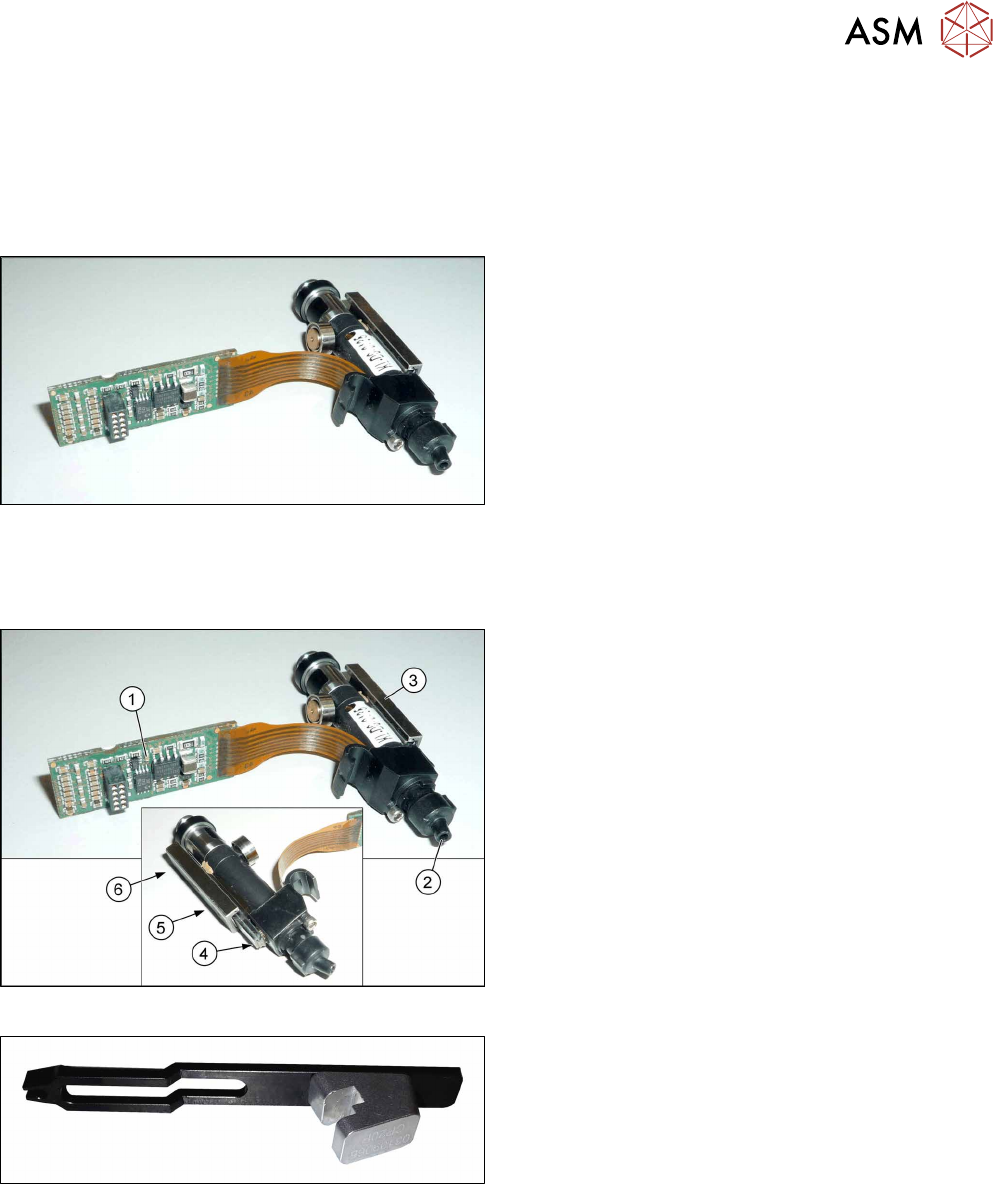
Fig.44: DP drive (example of SIPLACE C&P20P shown)
Select the correct DP drive:
●
For SIPLACE C&P20P:
DP drive SIPLACE C&P20P [03102532Sxx] (in-
cluding accessories)
●
For SIPLACE C&P20M2:
DP drive SIPLACE C&P20M2 assembly
[03153682Sxx] (including accessories)
●
If needed: DP vacuum hose for SIPLACE C&P20P [03103784‑xx]
Overview
Fig.45: DP drive (example of SIPLACE C&P20P shown)
1. Board
2. Connection for compressed air supply
3. Linear guide
4. End stop edge
5. Fastening screw
6. Fastening screw
Fig.46: DP change tool
●
DP change tool for the SIPLACE C&P20P
[03109065‑xx]
The DP change tool makes it easier to fit the DP drive
in the placement head.
5 DP drives
5.1 Replacing the DP drive
40 Service Manual SIPLACE SpeedStar (C&P20 P / C&P20 M2) 03/2018
Torques
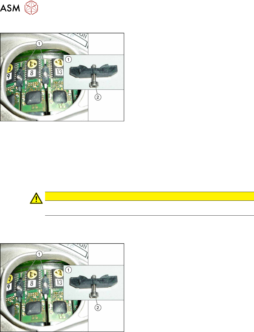
Fig.47: Clamping plate fastening screw
1. Clamping plates
2. Screw fastening the clamping plate
Torque: 0.1Nm
Preparation
► Remove the head from the machine. For details about removing and fitting the placement
head, refer to the service manual for your machine.
Fit the head on the head mount [03056231‑xx].
► Make sure that the component sensor protective cap is fitted.
1.1.3 "Safety instructions for the component sensor" [}6]
Removal
CAUTION
Tweezers, blunt 145mm size 3mm [00376493-xx]
Do not use any other tweezers for the hoses. If you do, the hoses could be damaged.
► Dismantle the holding circuit/aperture ring.
7.1 "Replacing the holding circuit/reflecting ring" [}61]
► Pull the nozzle off the segment.
Fig.48: Clamping plates
► Remove the screws(2) fastening the clamping
plates(1), on the right and left of the relevant DP
drive and take off the clamping plates.