00197490-03_SM_CP20-P-M2_EN保养维护.pdf - 第17页
3 Usability package 3.1 Usability package contents for SIPLACE C&P20P Service Manual SIPLACE SpeedStar (C&P20 P / C&P20 M2) 03/2018 17 3 Usability package Various modifications have been made to the SIPLACE …
2 Overview of the modules
2.2 Differentiation of the SIPLACE C&P20 head variants
16 Service Manual SIPLACE SpeedStar (C&P20 P / C&P20 M2) 03/2018
2.2 Differentiation of the SIPLACE C&P20 head variants
CAUTION
Do not confuse the different SIPLACE C&P20 head variants.
► Parts from the SIPLACE C&P20/A/M head can not usually be used for the SIPLACE
C&P20P/M2 head (and vice versa)!
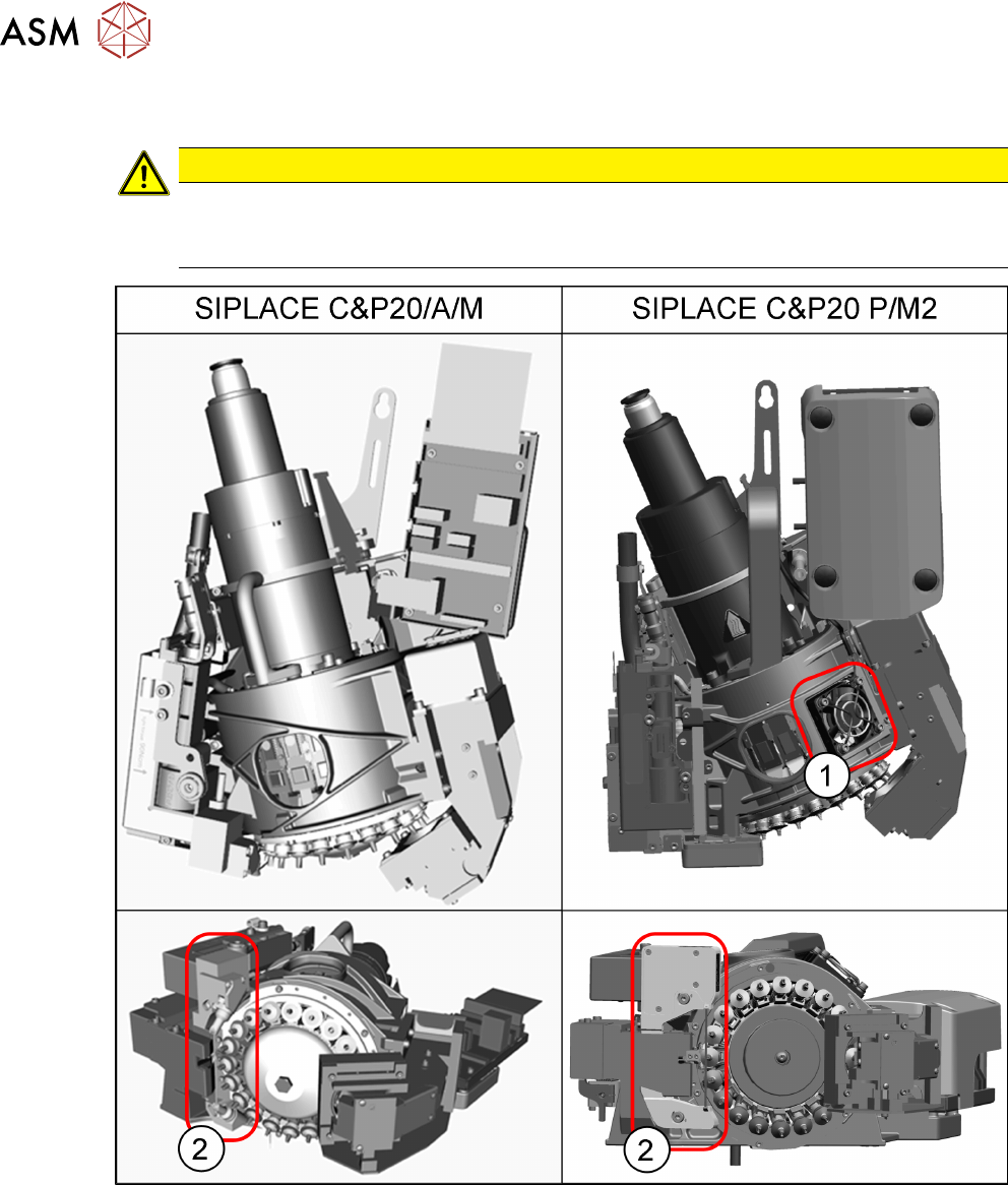
Fig.4: Differentiation of the SIPLACE C&P20 head variants
The SIPLACE C&P20/A/M and the SIPLACE C&P20 P/M2 head differ in many details. They are
easily identified by the following features:
1. The SIPLACE C&P20 P/M2 head can be identified by the fan. This fan is not present on the
SIPLACE C&P20/A/M.
2. The component sensor is flatter and wider on the SIPLACE C&P20 P/M2 than on the
SIPLACE C&P20/A/M.
3 Usability package
3.1 Usability package contents for SIPLACE C&P20P
Service Manual SIPLACE SpeedStar (C&P20 P / C&P20 M2) 03/2018 17
3 Usability package
Various modifications have been made to the SIPLACE C&P20P head, to make it easier to fit and
remove the SIPLACE Speedstar (C&P20P) placement head. These can be retrofitted as the so-
called "Usability Package for SIPLACE C&P20P".
3.1 Usability package contents for SIPLACE C&P20P
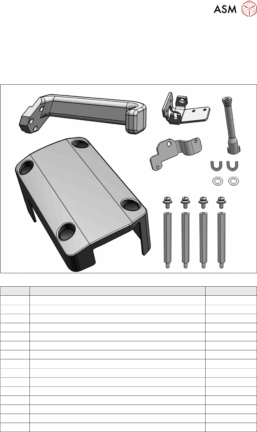
Fig.5: Overview of parts for SIPLACE C&P20P usability package [03122596‑xx]
Quantity Designation Master code
1 Board cover assembly for SIPLACE C&P20P 03113667-xx
4 Ball for press stud 03122667-xx
4 Spacer bolts type B i/a-M3x45-A2 03024207-xx
1 Head handle / plus - cast part 03127135-xx
1 Clamping plate for C&P20P 03117897-xx
2 Label 2 - assembly marking SIPLACE C&P20P 03122585-xx
2 Label 1 - assembly marking SIPLACE C&P20P 03122544-xx
1 Holding plate for FHE / CP20P 03117809-xx
1 Safety element RO SIPLACE C&P20P2 03139206-xx
2 ISO4762 - M1.6 x 6-A2-70 03042517-xx
3 ISO4762 - M3 x 12-A2-70 03042544-xx
2 ISO4762 - M2.5 x 4-A2-70 03042531-xx
2 ISO4762 - M2.5 x 8-A2-70 03042534-xx
2 ISO 4032 - M3-A2-70 03008162-xx
2 ISO10642 - M3 x 16-A2-70 03082818-xx
3 Usability package
3.2 Fitting the usability kit for SIPLACE C&P20P
18 Service Manual SIPLACE SpeedStar (C&P20 P / C&P20 M2) 03/2018
3.2 Fitting the usability kit for SIPLACE C&P20P
Preparation
► Remove the head from the machine. For details about removing and fitting the placement
head, refer to the service manual for your machine.
Fit the head on the head mount [03056231‑xx].
► Make sure that the component sensor protective cap is fitted.
1.1.3 "Safety instructions for the component sensor" [}6]
Conversion
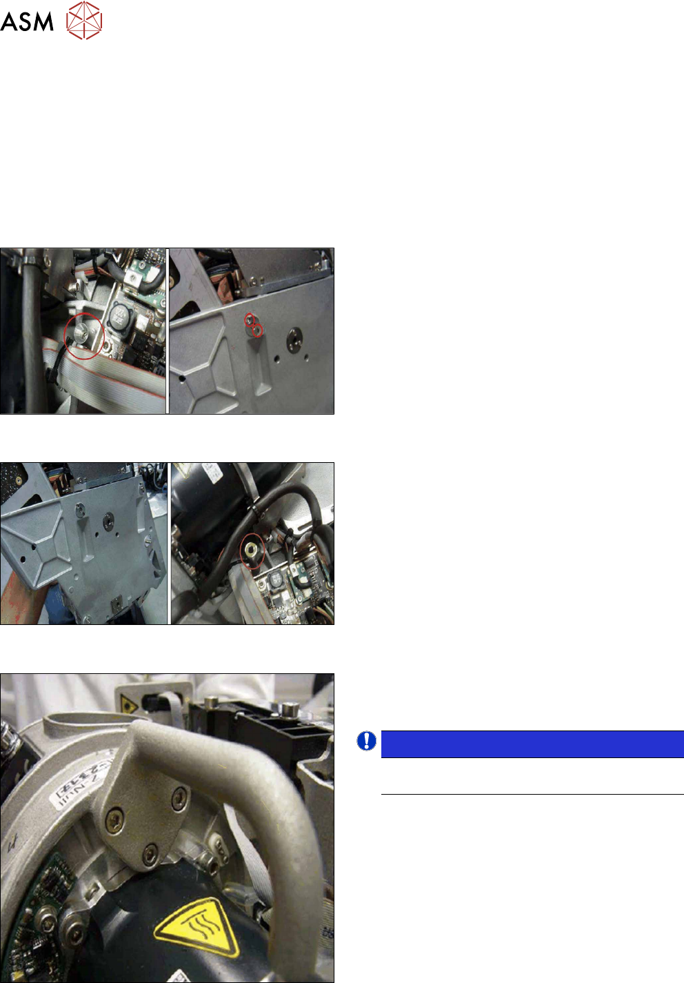
Fig.6: Replacing the safety element 1 (head front and back
sides)
► Remove the old safety element at the top right.
Fig.7: Replacing the safety element 2 (head front and back
sides)
► Fit the new "safety element RO SIPLACE
C&P20P2" [03139206‑xx] with two screws
(ISO4762-M1.6x6‑A2‑70), in place of the old
safety element.
Fig.8: Replacing the handle 1
► Dismantle the old handle. To do this, remove the
three hexagon socket fillister head screws
ISO4762M3x12
NOTICE!
The old screws can be reused for the new
handle.
.