00197490-03_SM_CP20-P-M2_EN保养维护.pdf - 第28页
4 Component camera, Z axis and component sensor 4.1 Replacing the component camera 28 Service Manual SIPLACE SpeedStar (C&P20 P / C&P20 M2) 03/2018 4.1.1 Board: LED driver BE VHS The "LED driver BE VHS"…
4 Component camera, Z axis and component sensor
4.1 Replacing the component camera
Service Manual SIPLACE SpeedStar (C&P20 P / C&P20 M2) 03/2018 27
Installation
► Fit the new component camera. Tighten the four fastening screws with a torque of 1.3Nm.
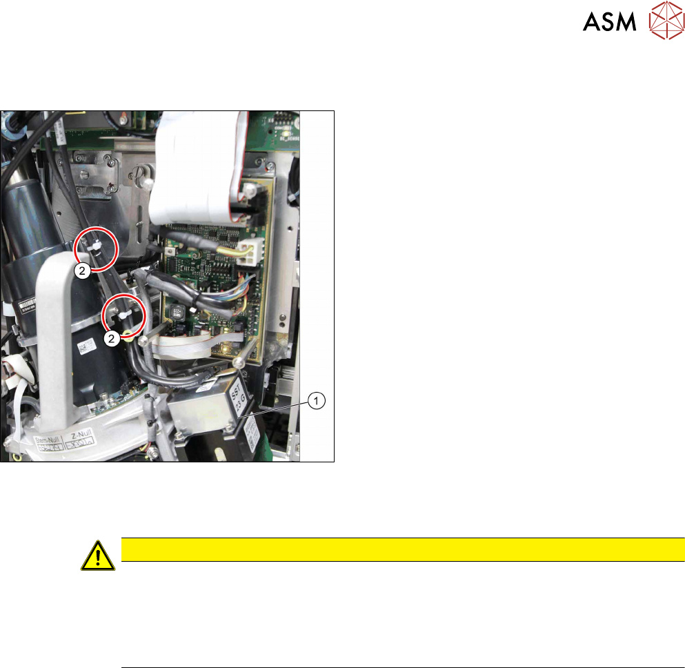
Fig.25: Cables for GigE camera
► Plug in the connection cable and fix it with cable
ties, where necessary. Pay particular attention to
the correct running of cables and positioning of
cable ties for GigE cameras.
► Follow the removal instructions in reverse order for further installation. Also observe the fol-
lowing instructions:
CAUTION
Installation instructions
► Calibrate the placement head.
This can be done using the FHE function. If the calibration data are stored in the cam-
era, a brief calibration is sufficient. If this is not the case, brief calibration will not be
suggested and standard calibration must be performed.
11.2 "Calibration" [}84]
4 Component camera, Z axis and component sensor
4.1 Replacing the component camera
28 Service Manual SIPLACE SpeedStar (C&P20 P / C&P20 M2) 03/2018
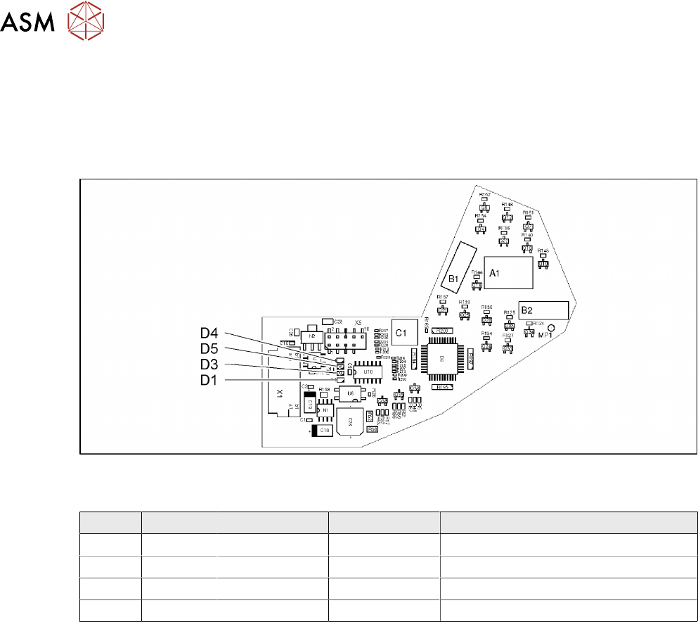
4.1.1 Board: LED driver BE VHS
The "LED driver BE VHS" board [03003002‑xx] is fitted in the following component cameras:
●
Component camera C&P (type23) 6x6 digital [03003426‑xx]
●
Component camera C&P (type41) 6x6 digital [03078957‑xx]
●
Component camera C&P (type43) 6x6 Hotlink [03122243‑xx]
Fig.26: 03003002-04
LEDs [03003002-04]
LED Color Status Signal name Description
D1 GN ON 40V_IN +40VDC operating voltage
D3 GN ON 15V+ +15VDC operating voltage
D4 GN ON 15V- -15VDC operating voltage
D5 GN ON 5V+ +5VDC operating voltage
4 Component camera, Z axis and component sensor
4.2 Replacing the Z axis cover
Service Manual SIPLACE SpeedStar (C&P20 P / C&P20 M2) 03/2018 29
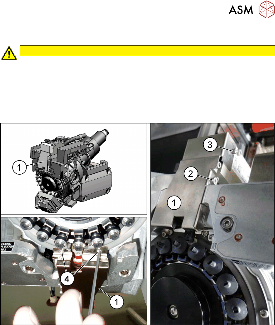
4.2 Replacing the Z axis cover
CAUTION
Sensitive lenses
The transmitter and receiver unit lenses on the component sensor are highly sensitive.
► Make sure that you do not damage or contaminate the lens system.
Parts
●
Bottom cover assembly for SIPLACE C&P20P [03093482Sxx]
Overview
Fig.27: Z axis cover
1 Z axis cover on the SIPLACE C&P20P 2 Fastening screw
(ISO4762‑M3x35‑A2‑70)
Washer (ISO7089-3-200HV-A2)
3 Fastening screw
(ISO4762‑M2.5x4‑A2‑70)
4 Two fastening screws on raceway
(ISO4762‑M2.5x4‑A2‑70)
Preparation
► Remove the head from the machine. For details about removing and fitting the placement
head, refer to the service manual for your machine.
Fit the head on the head mount [03056231‑xx].