00197490-03_SM_CP20-P-M2_EN保养维护.pdf - 第35页
4 Component camera, Z axis and component sensor 4.4 Replacing the cover flex Service Manual SIPLACE SpeedStar (C&P20 P / C&P20 M2) 03/2018 35 Installation Fig.39: Inserting the magnets (shown without the rest of…
4 Component camera, Z axis and component sensor
4.4 Replacing the cover flex
34 Service Manual SIPLACE SpeedStar (C&P20 P / C&P20 M2) 03/2018
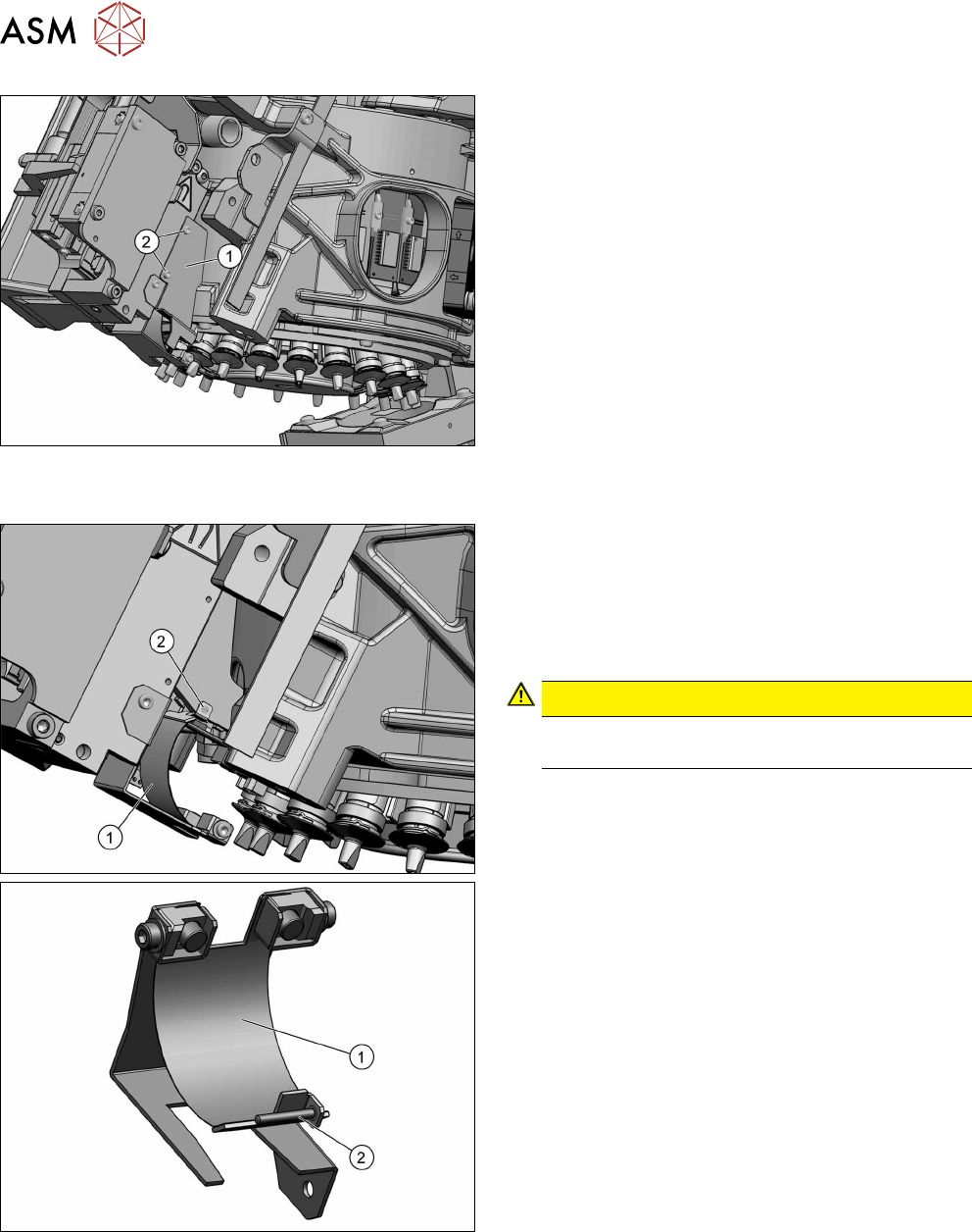
► Remove the two fastening screws(2) and then
take the side cover(1) off.
► Remove the two round magnets.
4.3 "Replacing the round magnets" [}31]
Fig.38: Screw fastening the cover flex
The cover flex(1) is fixed with a screw(2) (DIN8243 A
M1x8‑A2) and a clamping plate to the head. Depend-
ing on the head version, the clamping plate will be
loose or fixed to the frame.
► Remove the fastening screw and the clamping
plate and then take the cover flex out.
CAUTION!
Take care not to lose the screw and the
clamping plate opposite to this.
.
4 Component camera, Z axis and component sensor
4.4 Replacing the cover flex
Service Manual SIPLACE SpeedStar (C&P20 P / C&P20 M2) 03/2018 35
Installation
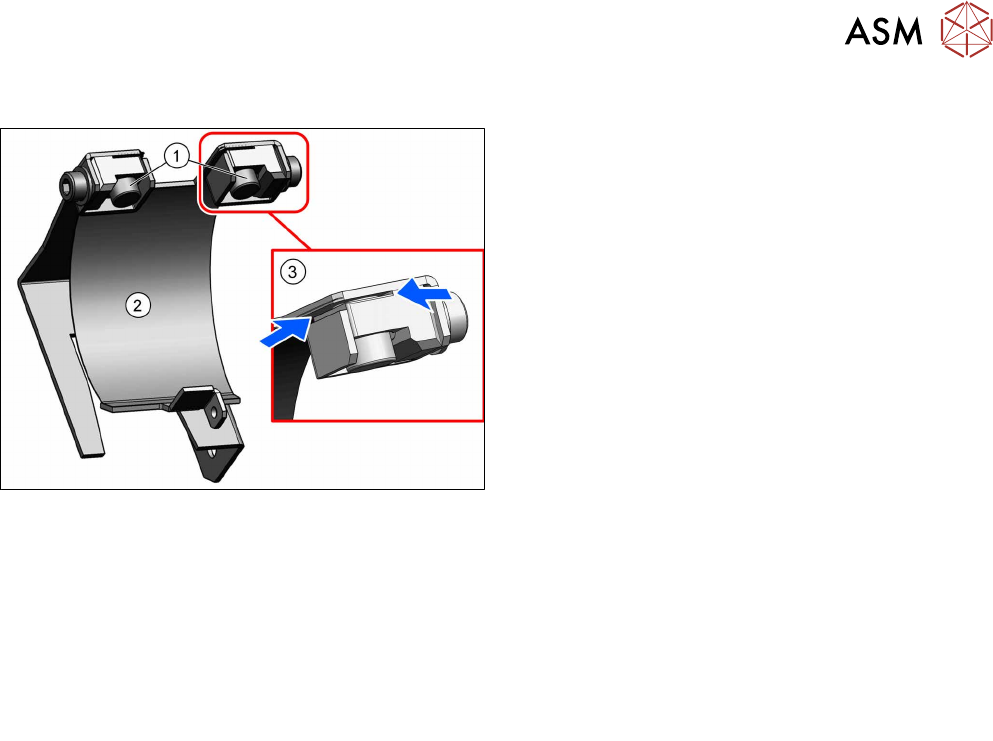
Fig.39: Inserting the magnets (shown without the rest of the
head)
► Insert the cover flex and fasten it to the head with
a screw (DIN8243 A M1x8‑A2).
► Make sure that the two ends of the cover flex(2)
are inserted properly into the slits(3).
► Fasten the cover flex with the two magnets(1).
► Follow the removal instructions in reverse order for further installation.
Also observe the installation instructions in the following sections:
4.3 "Replacing the round magnets" [}31]
6.1 "Replacing the PRV" [}47]
4.5 "Replacing the component sensor" [}36]
4.2 "Replacing the Z axis cover" [}29]
► Observe in particular the torques specified!
4 Component camera, Z axis and component sensor
4.5 Replacing the component sensor
36 Service Manual SIPLACE SpeedStar (C&P20 P / C&P20 M2) 03/2018
4.5 Replacing the component sensor
CAUTION
Sensitive lenses
The transmitter and receiver unit lenses on the component sensor are highly sensitive.
► Make sure that you do not damage or contaminate the lens system.
Parts
●
Component sensor for SIPLACE C&P20P [03092400‑xx]
Overview
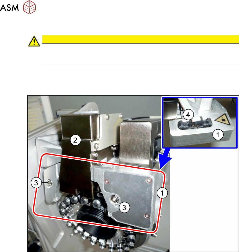
Fig.40: Component sensor and Z axis cover
1 Component sensor on the SIPLACE
C&P20P
2 Z axis cover
3 Two fastening screws for component
sensor
4 Electrical connection on component
sensor
Preparation
► Remove the head from the machine. For details about removing and fitting the placement
head, refer to the service manual for your machine.
Fit the head on the head mount [03056231‑xx].